
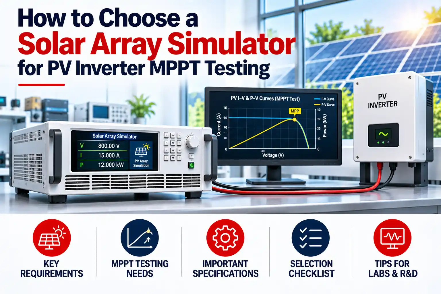
A microinverter or power optimizer must work when sunlight changes not only under one ideal laboratory condition. Testing it outdoors makes those changes difficult to control and repeat. An electrical solar array simulator gives engineers a way to apply defined photovoltaic (PV) input characteristics and run the same test again.
The buying decision starts with your device under test. Its input voltage, current and power requirements determine which simulator can connect to it. The test procedure then determines how accurately and quickly the simulator must reproduce changing solar conditions.
What does a solar array simulator do?
A solar array simulator is a programmable DC source that reproduces the electrical behaviour of a PV panel or array. Instead of holding only one fixed voltage, it can present an I–V curve: the relationship between output current and voltage as the connected device changes its operating point.
Four values help describe that curve:
- Voc: Open-circuit voltage
- Isc: Short-circuit current
- Vmp: Voltage at the maximum power point
- Imp: Current at the maximum power point
A PV inverter’s maximum power point tracking (MPPT) function tries to operate near the point where the array delivers its greatest power. Because sunlight and cell temperature affect the PV I–V curve, a repeatable test needs to account for more than a single voltage setting. NREL’s explanation of PV operation describes that relationship.
Why use one instead of a standard DC power supply?
A conventional programmable DC supply can provide controlled input power. That is useful for startup checks and other fixed-voltage tests. A solar array simulator is intended for tests where the device must respond to PV-like current and voltage behaviour as conditions change.
For example, you may want to observe whether a microinverter finds the maximum power point after an irradiance change, or how a power optimizer responds when part of an array is shaded. ITECH says its IT-N2100 series can generate static and dynamic I–V curves and simulate changes in light, temperature and shading.
The question for your lab is therefore: Do you need a controlled DC input, or must the input behave like a changing PV array?
Six specifications to check before choosing a simulator
1. Match voltage, current and power to the device under test
Record the full DC input range of the microinverter, optimizer or other device not just its nominal operating voltage. Then check the simulator’s voltage, current and power limits at the test points you plan to use.
| Model | Maximum output voltage | Maximum output current | Rated power |
|---|---|---|---|
| IT-N2121 | 80 V | 25 A | 800 W |
| IT-N2123 | 150 V | 10 A | 800 W |
| IT-N2131 | 80 V | 25 A | 1,500 W |
| IT-N2133 | 150 V | 10 A | 1,500 W |
Treat voltage, current and power as separate limits. Check that the chosen model supports the combination required at every point on your planned I–V curve.
A particularly important distinction: ITECH also lists a 1,500 V DC output-to-ground isolation rating for this series. That is not a 1,500 V output rating; the listed models have maximum outputs of 80 V or 150 V. For a higher-voltage string inverter, specify the input range first and ask for an appropriately rated PV simulation system.
2. Check how the simulator creates I–V curves
Ask whether you can enter the PV parameters required by your test procedure, load a defined curve and save it for repeat runs. For development work, you may need to compare several panel types or operating conditions rather than test one default profile.
The IT-N2100 supports setting an I–V curve with Voc, Isc, Vmp and Imp, as well as other curve and sequence options. Confirm that the available methods match the curves your engineering team intends to use.
3. Examine dynamic response for MPPT tests
A static curve can show how a device behaves at one condition. An MPPT test may also need the curve to change while the device is running for example, to represent a passing cloud or a change in irradiance.
Ask the supplier how quickly the proposed simulator updates its output and whether its response is suitable for your device’s MPPT behaviour. Also decide what you need to record: the programmed curve, actual voltage and current, tracked operating point, or a test report.
4. Decide whether you need multiple PV inputs
Some devices have more than one independent PV input. If your procedure calls for different conditions on each input, one simulator channel may not cover the whole test.
Specify the number of independently controlled channels and whether they must change together. ITECH lists multi-channel control software for the IT-N2100 series; confirm the required hardware and software configuration for your setup.
5. Check software, automation and data export
A manually run demonstration and a repeatable validation test have different needs. For the latter, ask how the system stores test profiles, controls sequences and exports results. Include any communication interface your existing test bench requires.
Write down the result you need at the end of the test. A live display may be enough for troubleshooting; engineering sign-off may require saved curves, time-stamped measurements and a repeatable test record.
6. Confirm protection and installation requirements
Check the proposed model’s protection functions, output connections, electrical input and cooling needs against your lab setup. Define the device’s limits and test stop conditions before commissioning the bench. Follow the manufacturer’s instructions and your approved procedure for connection and operation.
A practical test plan for a microinverter lab
Before requesting a quote, turn the application into a short test plan:
- Define the device: Model, number of PV inputs and permitted DC input range.
- Define the PV curves: The Voc, Isc, Vmp and Imp values or other curve data the test must reproduce.
- Define changing conditions: Irradiance, temperature or shading profiles, and how quickly they should change.
- Define the measurements: What will show whether the device tracked the intended maximum power point?
- Define the records: Profiles, measured values and reports needed for comparison between test runs.
This plan lets you compare equipment against the work your lab will actually perform. It also helps identify when a compact microinverter-focused simulator is suitable and when the application calls for a higher-voltage or higher-power system.
What should you ask when requesting a price?
“Solar array simulator price” is a useful starting question, but a meaningful quote depends on the configuration. Send the supplier your required output voltage, current, power, channel count, I–V curve functions, automation needs and test duration. Include the microinverter or optimizer’s input specifications and your required accessories.
You can review the IT-N2100 in Revine Tech’s ITECH range, then share those requirements to identify an appropriate model.
Choose from the test, not the headline rating
The right solar array simulator must cover your device’s electrical operating range and reproduce the PV behaviour your MPPT test needs. Start with the device specifications and test curves; then compare model ratings, dynamic response, channels and records.
Need help specifying a PV test bench? Send Revine Tech the device’s DC input range, power, number of PV inputs and required test profiles.
Request a Solar Array Simulator Quote
FAQs
Can the ITECH IT-N2100 test every PV inverter?
No single model should be assumed to fit every inverter. The IT-N2100 models listed by ITECH have maximum outputs of 80 V or 150 V, depending on configuration, and rated powers of 800 W or 1,500 W. Compare those limits with the inverter’s complete input and test requirements before selecting a model.
Is the IT-N2100’s 1,500 V isolation rating its output voltage?
No. The 1,500 V DC output-to-ground isolation specification is separate from the model’s rated output voltage. The IT-N2100 datasheet lists output voltage ratings of 80 V or 150 V by model.
Can a programmable DC supply be used for MPPT testing?
It may cover a limited test if you only need a controlled DC input. If the test requires repeatable PV I–V curves and changing irradiance or shading conditions, specify those functions explicitly when comparing supplies and solar array simulators.
How can Revine Tech help me choose a solar array simulator?
Share your inverter or power optimizer’s DC input range, power rating, number of PV inputs and required MPPT test profiles. Revine Tech can use those requirements to help shortlist a suitable ITECH configuration and provide a quote. Explore the ITECH range or contact Revine Tech.