2-Channel vs 4-Channel Oscilloscope: What's the Difference?
Introduction
Oscilloscopes are essential test and measurement instruments for visualizing electronic signals, but how many channels do you really need? The number of channels, meaning independent inputs, directly impacts what you can measure. More channels let you observe multiple waveforms simultaneously, revealing timing relationships and interactions you might otherwise miss. For electronics engineers and technicians working on embedded systems or power electronics, channel count can be as important as bandwidth or sample rate. This article explains why channel count matters when selecting an oscilloscope and breaks down the practical differences between 2-channel and 4-channel models. You will learn what you can and cannot do with more or fewer channels, how channel count affects debugging workflow and accuracy, what technical trade-offs exist around sample rate and memory sharing, and which choice fits real lab scenarios.
Understanding Oscilloscope Channels
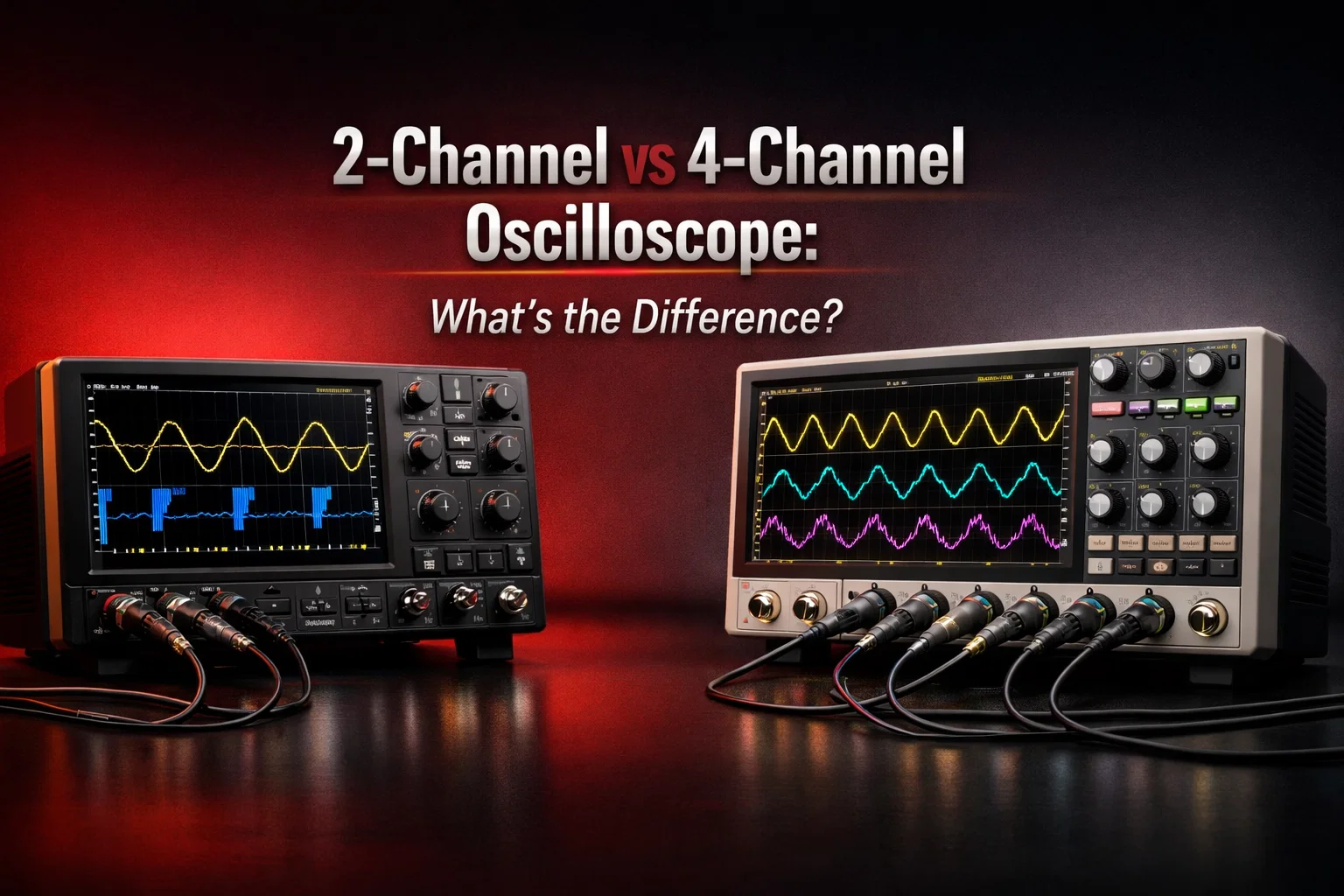
Channel count is simply the number of independent input channels available to connect probes and measure signals. Each channel has its own connector and analog front-end that conditions the signal before it is sampled and displayed. A 2-channel oscilloscope captures two signals at once, while a 4-channel scope captures four.
The value of multiple channels is time correlation. When signals are captured in the same acquisition, you can trust their relative timing. If signals are captured in separate acquisitions, you may not be able to confidently compare delays, ordering, or cause and effect, especially when a system has jitter, non-deterministic software timing, or intermittent faults.
Some oscilloscopes also include digital channels, typically in mixed-signal oscilloscopes. These add logic-level visibility across multiple digital lines while keeping a few analog channels for waveform shape, noise, rise time, and overshoot. In this blog, the focus is on analog channel count, which is the most common “2 vs 4” decision.
Signal Visibility and Debugging Capability
Channel count directly changes how much of the circuit you can see at once. With two channels, you can compare an input to an output, a signal to a reference, or a control signal to a measured response. Many everyday debugging tasks fall into this category, including checking amplifier response, validating basic sensor outputs, measuring PWM duty cycle, or viewing a clock alongside one data line.
A 4-channel oscilloscope becomes more valuable when the problem involves relationships between multiple signals. For example, many serial buses and control systems require several signals to be captured together to understand timing. In embedded systems, it is common to need to see a clock, a data line, a control or enable signal, and a power rail at the same time to understand what a device is doing and why it fails under certain conditions. When you can see these together, the scope becomes a diagnostic tool instead of just a signal viewer.
Triggering is also more flexible with more channels. A common approach is to trigger on one signal and observe a response on the remaining channels. With only two channels, triggering on a dedicated reference can consume half your visibility. With four, you can trigger on a control line and still observe three different responses. This matters when you are debugging sequences, such as reset events, power-good behavior, boot timing, or protection circuits.
Workflow Speed and Efficiency
A major difference between 2-channel and 4-channel oscilloscopes is not only capability, but time. When you have enough channels, you can connect everything once, configure triggers once, and capture the complete interaction in one acquisition. When you do not have enough channels, you often end up swapping probes and repeating captures. That slows you down and can hide intermittent issues.
The risk with probe swapping is that you stop seeing the system as it actually behaves. You see fragments captured at different times under different conditions, then try to mentally stitch them together. If the issue is rare or depends on multiple signals aligning in a certain way, sequential captures can be misleading. A 4-channel scope reduces this risk by capturing more context in one shot.
This advantage is most obvious in multi-rail and embedded systems. Power sequencing checks, reset root-cause analysis, and bus timing validation become far more straightforward when you can see several signals aligned to the same trigger event.
Accuracy of Results and Common Pitfalls
More channels provide more visibility, but measurement quality still depends on technique and on the oscilloscope’s acquisition architecture.
A common mistake is improper probing. Each probe adds capacitance and can introduce noise pickup if grounding is poor. Long ground leads can create loop inductance, causing ringing and false overshoot on fast edges. When you connect several probes at once, the chances of ground noise, measurement loading, and trace clutter increase. Good practice includes using short ground connections, using the right probe type for the job, and being consistent about reference points so that the waveforms remain comparable.
Another pitfall is under-sampling. Many oscilloscopes cannot maintain the same sample rate when all channels are enabled. The maximum sample rate printed on a product overview often assumes one channel active, and the scope may divide sampling resources as you enable more channels. If your sampling rate drops, narrow glitches or high-frequency content can be missed. This can create false confidence because the waveform looks clean simply because the scope did not capture enough points to reveal the problem.
Memory depth can have similar behavior. Some scopes effectively share memory across channels. With more channels enabled, memory per channel can drop, reducing capture length at a given sample rate. When you need long captures to see sequences and still need good time resolution, memory depth becomes a real constraint.
The opposite mistake can happen when you only have two channels and you try to compare signals captured at different times. The system may not behave identically between acquisitions. If software timing changes slightly, or if the fault is intermittent, you can reach the wrong conclusion about timing relationships. This is one of the strongest arguments for using enough channels to capture the complete event together.
Technical Trade-offs: Bandwidth, Sample Rate, and Architecture
Channel count is not the only factor, because a 2-channel and a 4-channel model at similar budget levels may differ in bandwidth, sample rate behavior, noise performance, and memory.
In many product families, the 2-channel model may offer higher bandwidth for the same price, or maintain higher sample rate with both channels active, while the 4-channel model may trade some per-channel performance to include extra inputs. This is not always true, but it is common enough that you should check specifications carefully. If you work with fast digital edges, high-speed clocks, or RF-related time-domain measurements, bandwidth and sample rate may matter more than having four channels available at once.
Sample rate sharing is one of the key architectural points. Some scopes use interleaving to achieve high sample rates, meaning ADC resources are shared. When one channel is active, it can use the full digitizer. When multiple channels are active, the digitizer is split and effective sample rate per channel drops. Higher-end scopes may provide more independent resources so this effect is reduced, but the best approach is to verify the “sample rate with all channels active” specification.
Memory depth can also impact how usable the oscilloscope is in multi-channel debugging. For long sequences, like boot events or long protocol bursts, you want sufficient memory to maintain time resolution across the entire capture. If memory per channel drops significantly when four channels are enabled, you may be forced into lower sample rates for long captures, which can again hide high-speed details.
These trade-offs are not arguments against 4 channels. They are a reminder that the best choice is a system-level choice. You want enough channels and enough per-channel performance for your real measurements, not just the biggest channel number on the front panel.
Real-World Use Cases: When 2 Channels Suffice
Two channels are enough when your measurement goal is naturally framed as a comparison between two points or two signals.
In basic analog work, you often need to see input and output together. In power troubleshooting, you might check a rail’s ripple and compare it to load or control behavior. In simple embedded work, you may only need to view a UART line or capture an I2C clock and data line together. In educational labs, 2 channels also reduce complexity and keep attention focused on core waveform behavior, scaling, triggering, and measurement technique.
Two channels can also be enough if you routinely use other tools for multi-line digital visibility. Many engineers pair a 2-channel oscilloscope with a logic analyzer for digital buses. In that approach, the oscilloscope is used where analog fidelity matters, such as edge integrity, ringing, overshoot, analog noise coupling, or power rail droop, while the logic analyzer captures multiple digital lines and decodes protocols over long durations.
Real-World Use Cases: When 4 Channels Become Necessary
Four channels become important when the system behavior depends on multiple signals interacting, and when seeing the complete timing relationship saves time and prevents wrong conclusions.
In embedded systems, SPI is the classic example because you ideally want to see clock, chip select, MOSI, and MISO together. With four channels, you can verify polarity, phase, setup and hold behavior, and response timing in one view. In more complex bring-up, you may also need to observe a reset line or an interrupt, and you will quickly appreciate that four channels is not “extra,” it is just enough.
In multi-rail systems, four channels let you capture the full story of a reset or brownout event. You can observe a main rail, a secondary rail, a power-good signal, and a reset line together, then immediately see whether the reset is a cause or an effect, and which rail actually dips first.
In power electronics, four channels often map naturally to control and response. You may need to observe a gate drive, a switching node, a current measurement, and output ripple. If you only measure two at a time, you may miss the relationship between current spikes and output behavior or between gate timing and switching stress. Capturing these together can reveal dead-time issues, ringing, transient behavior, and stability problems far faster.
In validation and QA workflows, four channels also reduce repeated test runs. When you are measuring timing across multiple signals to confirm compliance or design intent, it is more efficient to set up once and capture everything rather than repeating measurements and hoping the system behaves consistently across runs.
How to Decide: A Practical Perspective
Choosing between a 2-channel vs 4-channel oscilloscope should be based on the complexity of the systems you debug and the kinds of questions you ask during troubleshooting.
If your measurements are usually one signal at a time or a straightforward comparison between two points, and you rarely need to correlate more than two events, a 2-channel scope is a solid and cost-effective choice. It can also be the right choice if you prioritize bandwidth and per-channel sampling performance within a fixed budget.
If you frequently debug embedded interfaces beyond simple UART and I2C, if you work with multi-rail boards and sequencing, or if you handle power electronics where control and switching behavior must be correlated, a 4-channel scope usually pays for itself in time saved and confidence gained.
The smartest approach is to look at your last ten debugging sessions. If you repeatedly wished you could see “just one more signal” at the same time, that is strong evidence that two channels are limiting you. If you rarely feel constrained, a strong 2-channel model with good probes and adequate bandwidth can be the better investment.
Conclusion
The difference between 2-channel and 4-channel oscilloscopes is not just a number on a spec sheet. It changes how you observe system behavior, how reliably you can correlate signals in time, how fast you can find root causes, and how likely you are to miss intermittent issues. A 2-channel oscilloscope is often enough for basic analog work, education, and many simple embedded tasks. A 4-channel oscilloscope becomes valuable when you need full system context, especially for serial buses, power sequencing, and power electronics debugging.
Make the decision based on your real measurement workflows, and ensure that whichever channel count you choose, the oscilloscope’s bandwidth, sample rate behavior with multiple channels active, memory depth, and probe quality match the signals you need to trust.
FAQ
Is a 4-channel oscilloscope always better than a 2-channel oscilloscope?
Not always. If the 4-channel model compromises bandwidth, effective sample rate with all channels active, or memory depth per channel relative to a high-quality 2-channel option, the 2-channel scope can be a better fit for fast-edge work. The right choice depends on your measurements.
Do 4-channel oscilloscopes always reduce sample rate when all channels are enabled?
Not always, but many do. Some architectures share acquisition resources. Always check the specification for sample rate with one channel active and with all channels active.
Can I debug SPI with a 2-channel oscilloscope?
You can, but it is slower and riskier for timing correlation because you will not see all lines together. A 4-channel oscilloscope provides a clearer picture for full SPI validation.
What matters more: channel count or memory depth?
Both matter. If you are capturing long events like boot sequences or rare glitches, memory depth is critical. If you need to correlate multiple signals during the same event, channel count is critical. The best scope balances both for your use case.
If I use a logic analyzer, do I still need 4 oscilloscope channels?
Sometimes yes. Logic analyzers are great for digital state and timing across many lines, but they do not show analog signal quality like ringing, overshoot, rise time, or power rail droop. A common setup is a 2-channel oscilloscope plus a logic analyzer, but for mixed analog-digital interactions, four analog channels can still be very useful.
When should I consider a mixed-signal oscilloscope instead of a 4-channel analog scope?
If your main limitation is needing many digital channels for buses or multiple GPIO lines, a mixed-signal oscilloscope can be more efficient. If you mainly need analog visibility across multiple signals, a 4-channel analog scope is usually the better match.