Thermal imaging is a non-contact technology that captures invisible infrared radiation emitted by objects and converts it into a visual, color-coded image. This allows you to see and measure temperature differences, making heat patterns instantly visible.
In the world of modern electronics, success is measured in microns, megawatts, and microseconds. Whether you’re designing the next generation of semiconductors, ensuring quality on a high-speed production line, or maintaining mission-critical systems, the challenges are immense. At Revine Tech, we partner with engineers, technicians, and researchers across India, providing the advanced test and measurement tools needed to turn these challenges into innovations.
One of the most transformative technologies in our arsenal is thermal imaging. It’s more than just a way to see if something is hot; it’s a window into the operational health of an electronic system. A simple multimeter can tell you if a circuit has continuity, but it can’t show you the subtle, system-wide effects of a component under stress. A thermal imager can.
This guide is for the hands-on professional. We’re going to skip the fluff and dive straight into how a professional-grade Fluke thermal imager can become one of the most valuable tools in your kit. We’ll cover how the technology works, why specific features matter, and explore five practical applications where it can save you time, prevent catastrophic failures, and improve your bottom line.
How Does Thermal Imaging Work? Making the Invisible Visible
Before we get into the applications, let’s quickly cover the science. It’s simpler than you might think and understanding it is key to getting accurate results.
Every object with a temperature above absolute zero ($-273.15$ °C) gives off thermal energy. This energy travels as infrared (IR) radiation, a part of the electromagnetic spectrum that’s invisible to the human eye. The core principle is straightforward: the hotter an object is, the more infrared radiation it emits. A thermal imaging camera is essentially a sensor designed to see and measure this invisible IR energy.
Here’s a step-by-step breakdown of how a Fluke imager turns that invisible energy into an actionable image, called a thermogram:
- Energy Capture: A specialized lens, often made from a material like Germanium, focuses the infrared energy from the objects in its view onto a detector.
- Detection: The detector is an array of thousands of microscopic sensors called microbolometers. As each microbolometer absorbs IR energy, its temperature changes, which in turn changes its electrical resistance.
- Signal Processing: The camera’s processor scans this array thousands of times per second, measuring the resistance changes for each pixel and converting that data into a precise temperature map.
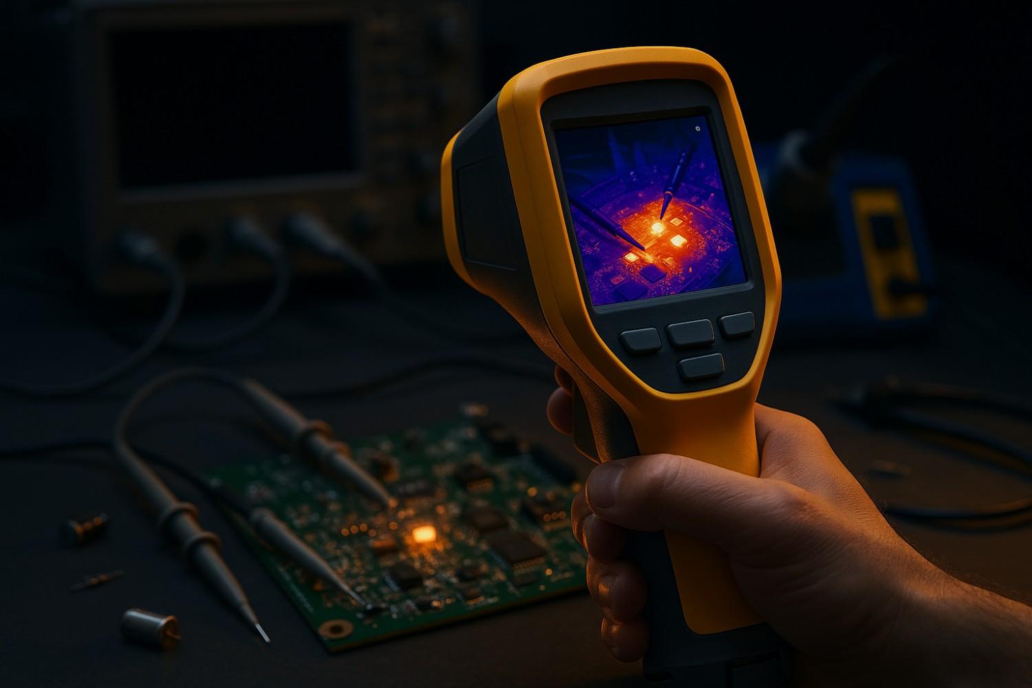
- Image Creation: The processor assigns a specific color to each temperature value based on a selected color palette (e.g., blues for cool, reds and yellows for hot). This creates the final thermal image you see on the screen.
For an electronics professional, this process is revolutionary. Heat is a direct byproduct of electricity in action. When current flows through a circuit, it generates heat due to resistance. Therefore, a thermogram of a printed circuit board (PCB) or an electrical panel isn’t just a heat map; it’s a direct, non-contact visualization of how your entire system is dissipating power. A "hot spot" is a clear, visual clue that points directly to an electrical anomaly, like a loose connection or a failing component.
Why a Fluke Imager? Key Features for the Electronics Professional
While many cameras can create a thermal image, professional electronics work demands a higher level of accuracy, context, and durability. Fluke thermal imagers are engineered not just to see heat, but to provide clear, quantifiable data that you can trust in demanding environments. Here are a few features that make a significant difference.
- IR-Fusion™ Technology: A common headache in thermal analysis is figuring out exactly which tiny component on a dense PCB corresponds to a hot spot. Fluke’s IR-Fusion™ technology solves this by capturing a visible light image and an infrared image at the same time. You can then blend the two images on-screen, overlaying the thermal data directly onto the visible image with perfect alignment. This gives you unambiguous context, letting you read component labels and immediately identify the source of the heat.
- LaserSharp™ Auto Focus: An out-of-focus thermal image can lead to temperature readings that are off by as much as 20 degrees, a critical margin of error in electronics. Fluke’s LaserSharp™ Auto Focus uses a built-in laser to calculate the precise distance to your target and automatically adjusts the focus. This ensures you get a sharp, clear image and, more importantly, a highly accurate temperature measurement every time.
- High Resolution and Thermal Sensitivity (NETD): When you’re inspecting a board packed with tiny surface-mount components, image detail is everything. Detector resolution (the number of pixels) determines how well you can distinguish between two adjacent heat sources. Fluke offers a range of resolutions, from pocket-sized 120x90 imagers to high-performance 640x480 models for detailed R&D work. Just as important is thermal sensitivity (NETD), which measures the smallest temperature difference the camera can detect. A lower NETD means the camera can spot very subtle thermal anomalies that are often the earliest signs of a developing fault.
- Fluke Connect® Software Ecosystem: Capturing an image is only half the battle. Documenting your findings and tracking trends over time is what turns data into a maintenance strategy. Fluke imagers integrate seamlessly with Fluke Connect® software, allowing you to wirelessly transfer images, add voice annotations, tag assets for easy organization, and generate professional reports. This streamlined workflow saves hours of administrative work and makes it easy to build a historical baseline for predictive maintenance.
Choosing the Right Fluke Imager for Your Needs
The right tool depends on the job. A quick field inspection has different needs than in-depth laboratory analysis. Here’s a quick comparison to help you match the tool to the task.
|
Feature |
Fluke PTi120 (Pocket) |
Fluke TiS60+ (Handheld) |
Fluke RSE600 (Mounted R&D) |
|
IR Resolution |
120 x 90 pixels |
320 x 240 pixels |
640 x 480 pixels |
|
Thermal Sensitivity (NETD) |
≤ 60 mK |
≤ 45 mK |
≤ 40 mK |
|
Temperature Range |
-20 °C to 400 °C |
-20 °C to 400 °C |
-25 °C to 1200 °C |
|
Focus System |
Fixed Focus |
Manual Focus |
Manual / Auto Focus |
|
Key Feature |
Ultimate Portability, Asset Tagging |
Rugged Design, IR-Fusion™ |
High-Speed Data Streaming for Analysis |
|
Ideal Application |
Frontline troubleshooting, quick electrical checks |
Predictive maintenance, detailed system inspections |
R&D, semiconductor analysis, process monitoring |
The 5 Core Applications in Electronics
Now, let’s get to the practical side. Here are five areas where a Fluke thermal imager can fundamentally change how you work, making you faster, safer, and more effective.
1. PCB Diagnostics and Fault Finding
The Problem: You power up a new prototype board, and the power supply immediately shows an overcurrent fault. Nothing feels hot to the touch, and probing around with a multimeter doesn’t reveal an obvious short circuit. You’re now facing hours of tedious, point-by-point searching.
The Thermal Imaging Solution: Instead of a slow, manual search, a thermal camera gives you an instant, board-level overview of power dissipation. Within seconds, you can:
- Pinpoint Overheating Components: A shorted capacitor or a faulty voltage regulator will light up like a beacon on the thermogram, immediately guiding you to the source of the excessive current draw.
- Trace High-Current Paths: Sometimes the fault isn’t a component but a short circuit downstream. The PCB trace carrying the excess current will heat up due to resistance. A thermal camera allows you to literally see this glowing trace and follow it directly to the location of the short.
- Identify "Cold" Failures: The absence of heat is just as telling. If a part of the circuit should be active but appears cold (at ambient temperature), it points to a problem like a broken trace, a cold solder joint, or a failed upstream component that isn't supplying power.
- Validate Thermal Design: Beyond finding faults, you can verify your thermal management strategy. A thermal image clearly shows how effectively heatsinks and copper planes are pulling heat away from critical ICs. You might spot a temperature gradient across a single chip, indicating poor thermal connectivity on one side, a design flaw that could impact long-term reliability.
This isn’t just faster; it’s a fundamentally better way to troubleshoot. It transforms the process from a linear guessing game into a parallel, data-driven analysis, dramatically cutting down R&D time.
2. IC and Semiconductor Development
The Problem: As transistors shrink and chip densities skyrocket, heat has become a primary limiting factor in performance and reliability. Traditional contact probes like thermocouples are often too large for modern ICs and can act as heatsinks themselves, altering the temperature of the very thing you’re trying to measure.
The Thermal Imaging Solution: A high-resolution thermal camera provides the non-contact, high-fidelity data needed to push the boundaries of semiconductor design. Engineers in R&D and validation labs use it to:
- Identify Microscopic Hotspots: Validate thermal simulation models by comparing them to real-world temperature maps of a functioning chip. This allows designers to find and fix unexpected hotspots early in the design cycle, optimizing the layout for better thermal performance.
- Monitor Manufacturing Processes: In chip fabrication, processes like deposition and annealing are extremely temperature-sensitive. Fixed-mount thermal cameras can monitor these steps in real-time to ensure temperature uniformity, which is critical for maximizing yield and ensuring quality.
- Evaluate Performance Under Load: Verify a chip’s thermal stability by monitoring its temperature in real-time as it runs different workloads. This provides crucial data to ensure the chip operates safely and reliably in its final application, preventing issues like thermal throttling.
In this high-stakes field, thermal imaging isn’t just a convenience; it’s an enabling technology that allows for continued innovation in performance and miniaturization.
3. Proactive Failure Prevention in Power Electronics
The Problem: In systems like industrial motor drives, EV chargers, and uninterruptible power supplies (UPS), a component failure can be catastrophic. It can lead to massive downtime, equipment damage, and serious safety risks like arc flash. Inspecting these high-voltage systems while they are energized is inherently dangerous.
The Thermal Imaging Solution: A thermal imager is a game-changer for safety and reliability in power electronics. It allows technicians to inspect energized equipment from a safe distance, identifying problems before they escalate. Common failure modes that are invisible to the naked eye become glaringly obvious on a thermogram:
- High-Resistance Connections: The most common cause of electrical failures is a poor connection. A loose or corroded terminal generates intense, localized heat as current flows through it. This appears as a distinct hot spot that cools as you move away from the point of high resistance.
- Component Degradation: Power components like MOSFETs and IGBTs run hotter as they age and degrade. A thermal scan can quickly compare identical components and identify the one that is running abnormally hot, flagging it for replacement before it fails completely.
- Load Imbalances: In a three-phase system, a fault or an unbalanced load will cause one phase to run significantly hotter than the other two. This thermal asymmetry is immediately visible and signals a serious problem that needs urgent attention.
Here, the thermal imager acts as a critical piece of personal protective equipment (PPE). The ability to safely inspect live, high-energy systems without physical contact fundamentally reduces risk for maintenance personnel.
4. Enhancing Quality Control in Electronics Manufacturing
The Problem: In high-volume manufacturing, traditional quality control often happens at the end of the line. By the time a defect is found, you’ve already wasted materials, energy, and production time on a faulty unit.
The Thermal Imaging Solution: Thermal imaging allows you to shift from reactive inspection to proactive, real-time process control. By installing fixed-mount cameras like the Fluke RSE series on a production line, you can monitor thermally sensitive processes 24/7. This enables:
- Real-Time Process Monitoring: For processes like reflow soldering, adhesive curing, or injection molding, precise temperature is key to quality. A thermal camera provides a continuous data stream, ensuring the process stays within spec and allowing for immediate adjustments.
- Automated Defect Detection: Many manufacturing defects have a unique thermal signature. In battery manufacturing, for example, inconsistencies in electrode coatings can be spotted thermally. In welding, an incomplete seal will appear as a cool spot.
- AI-Powered Quality Assurance: The thermal data can be fed into an AI system trained to recognize the thermal signature of a "perfect" product. The system can then automatically flag any unit that deviates from this baseline, enabling 100% inspection at high speed and preventing entire batches of defective products from being made.
According to a 2024 study on quality control in battery manufacturing, thermal imaging combined with machine learning can predict the mass loading of electrode coatings with high accuracy, directly improving production reliability. By monitoring the process instead of just the product, you prevent defects from happening in the first place.
5. Predictive Maintenance for Mission-Critical Systems
The Problem: The old model of maintenance is either reactive (fix it when it breaks) or preventative (fix it on a schedule, whether it needs it or not). Both are inefficient. The goal of a modern strategy is predictive maintenance (PdM): performing maintenance at the right time, just before a failure occurs.
The Thermal Imaging Solution: Thermal imaging is a cornerstone of any effective PdM program. The process is systematic and data-driven:
- Establish a Baseline: When a critical asset (like a data center PDU or a factory motor control center) is running correctly, capture a set of thermal images. This is your "normal" thermal signature.
- Conduct Regular Inspections: On a set schedule (e.g., quarterly), capture new images under similar load conditions. For electrical systems, it’s crucial to inspect when the system is under at least 40% load, as problems may not be visible otherwise.
- Analyze the Trend: Using software like Fluke Connect®, compare the new images to the baseline. A component whose temperature has been steadily rising over several inspections is a clear sign of degradation and impending failure.
- Act Proactively: This trend data allows you to schedule a repair during planned downtime, avoiding a costly and disruptive emergency failure.
Most experts agree that a well-run PdM program can deliver a return on investment of up to 10 times by reducing maintenance costs by 25-30% and eliminating 70-75% of breakdowns. The thermal imager is your primary data collection tool for this powerful strategy.
Getting It Right: Best Practices for Accurate Thermal Data
A Fluke thermal imager is a precision instrument, but its accuracy depends on the operator. Simply pointing and shooting isn’t enough. To get reliable data, you need to be aware of a few key principles.
- Understand Emissivity: This is the single most important factor for accurate temperature measurement. Emissivity is a measure of how well a surface radiates heat. A matte black surface has high emissivity (around 0.95) and gives an accurate reading. A shiny, reflective surface like a solder joint or copper bus bar has very low emissivity. A low-emissivity surface will reflect the heat from its surroundings (including your own body heat), giving you a completely false reading.
- The Fix: For qualitative checks, compare similar components. The one that is relatively hotter is the problem. For an accurate absolute temperature, apply a small piece of black electrical tape (which has a known high emissivity of ~0.97) to the shiny surface and measure the tape.
- Focus is Critical: As mentioned earlier, an out-of-focus image will give you an inaccurate temperature reading. Always take the time to ensure your image is sharp. Features like Fluke’s LaserSharp™ Auto Focus are designed to eliminate this common source of error.
- Load Matters: Electrical faults only generate significant heat when current is flowing. Inspecting a system that’s idle or under a light load won’t reveal much. Always inspect systems running at 40% of their normal load or higher.
The Takeaway: Which Thermal Imager is Right for You in 2025?
Thermal imaging is no longer a niche technology for specialized labs. It is a versatile, powerful diagnostic tool that provides critical insights across the entire lifecycle of electronic products. From accelerating R&D and improving manufacturing quality to ensuring safety and preventing downtime, a Fluke thermal imager is a strategic investment that delivers a clear and compelling return.
By making the invisible world of heat visible, you empower your team to find problems faster, build more reliable products, and maintain systems more intelligently. It’s a shift from reacting to problems to proactively preventing them. This is a shift that is essential for staying competitive.
As technology evolves, Fluke continues to lead with more powerful sensors and smarter software. Check back with us at Revine Tech each quarter for updates on the latest models and features to keep your operations at the cutting edge.
Ready to see the heat in your own systems? Explore our full range of products, from the pocket-sized PTi120 to high-performance models for detailed analysis.
Have questions or need a personalized recommendation? Contact us to discuss your specific challenges and find the perfect thermal imaging solution for your application.