
.jpg)
.jpg)

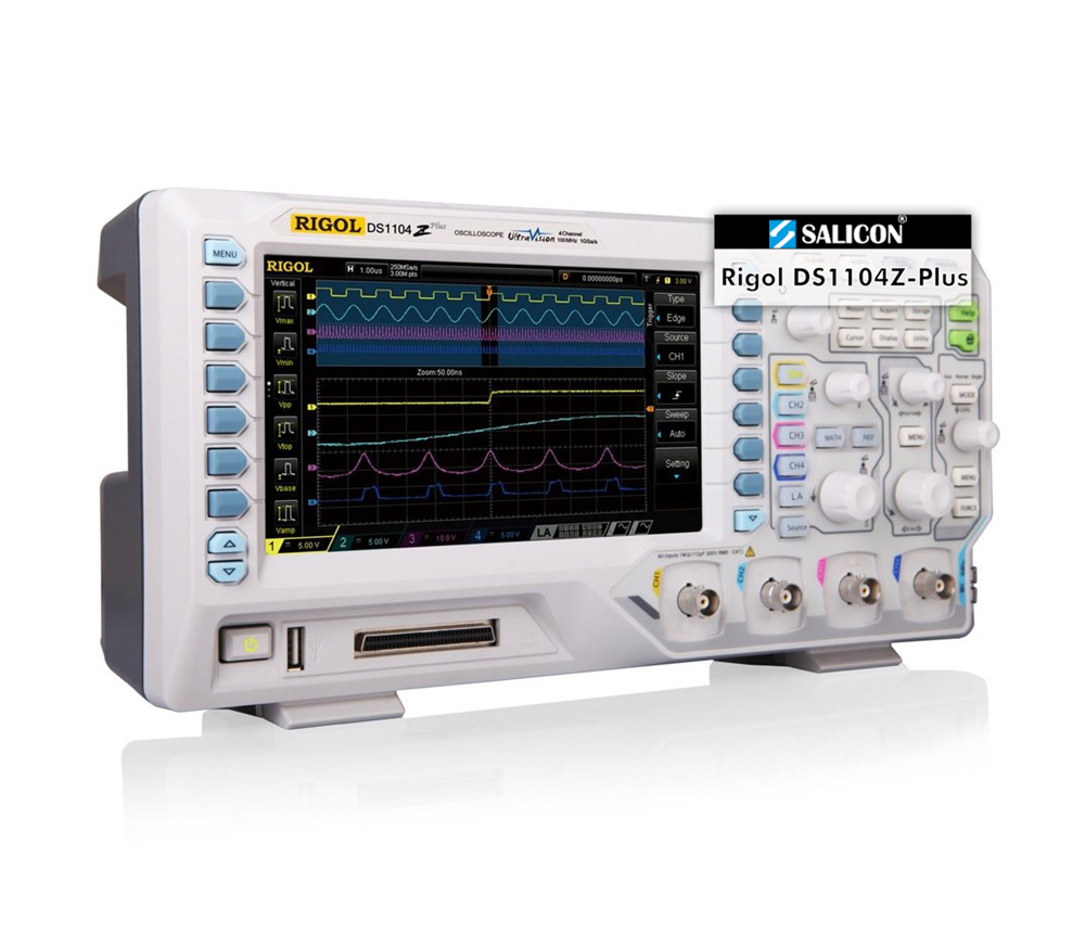
Rigol DS1104Z Plus
Precision You Can Trust
NABL-Accredited Calibration | Available on Request
Rs. 65490.00
The RIGOL DS1104Z Plus is a 100 MHz, four-channel digital oscilloscope designed for embedded-system debugging, electronics development, power-supply testing, maintenance and education. It delivers up to 1 GSa/s real-time sampling, 12 Mpts standard memory, optional expansion to 24 Mpts, waveform capture up to 30,000 wfms/s and optional 16-channel logic analysis through the RPL1116 probe on a 7-inch colour display..
The RIGOL DS1104Z Plus Digital Oscilloscope is designed for engineers, technicians, research laboratories, educational institutions and electronics service teams that require four-channel analogue measurements with the flexibility to add mixed-signal analysis.
The instrument provides 100 MHz analogue bandwidth, four analogue input channels and a maximum real-time sampling rate of 1 GSa/s. Its built-in digital interface supports up to 16 logic channels when the optional RPL1116 logic probe is connected.
RIGOL UltraVision technology combines deep acquisition memory, intensity-graded waveform display, fast waveform capture, waveform recording and advanced analysis functions. These capabilities help users detect repetitive waveform behaviour and intermittent faults such as glitches, runt pulses, unstable edges and timing violations.

100 MHz Analogue Bandwidth
The DS1104Z Plus provides 100 MHz bandwidth across four analogue channels. Its calculated rise time is approximately 3.5 ns.
It is suitable for analysing:
- Microcontroller clock and control signals
- FPGA and CPLD outputs
- PWM and pulse waveforms
- Switching power-supply signals
- Sensor and actuator outputs
- Analogue amplifier circuits
- Embedded communication interfaces
- Timing and phase relationships
- Input and output waveform behaviour
- General signal-integrity problems
Actual measurement performance also depends on probe bandwidth, grounding method, signal rise time, source impedance and connection quality.

Four Analogue Input Channels
The four-channel architecture allows users to observe several related signals simultaneously.
Typical measurements include:
- Clock, data and enable signals
- Input and output waveforms
- Voltage and current correlation
- Multiple power rails
- Sensor signal and controller response
- High-side and low-side control signals
- Reference and measured waveforms
- Multi-stage start-up sequences
- Phase and delay between signals
Four analogue inputs are particularly useful when debugging systems where one event affects several circuit sections.
Optional 16-Channel Logic Analysis
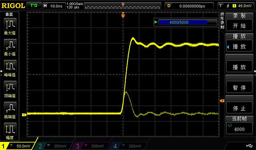
The Plus-series digital interface supports up to 16 digital input channels through the optional RPL1116 logic probe.
This mixed-signal capability supports:
- Microcontroller GPIO debugging
- FPGA and CPLD testing
- Parallel bus analysis
- Digital timing measurements
- Clock and data correlation
- Time-correlated analogue and digital display
- Digital control-system troubleshooting
- Observation of power behaviour during logic switching
Digital sampling performance is:
- Up to 1 GSa/s with eight digital channels active
- Up to 500 MSa/s with all 16 digital channels active
The minimum detectable digital pulse width is approximately 10 ns. The RPL1116 logic probe should be listed separately unless it is confirmed as part of the supplied commercial package.
Channel-Dependent Analogue Sampling
The DS1104Z Plus provides a maximum real-time analogue sampling rate of 1 GSa/s.
Sampling allocation is:
- 1 GSa/s with one active analogue channel
- 500 MSa/s per channel with two active analogue channels
- 250 MSa/s per channel with three or four active analogue channels
Engineers should consider this allocation when measuring fast signals on several channels simultaneously.
Sampling rate, oscilloscope bandwidth, signal frequency and signal rise time collectively determine waveform representation quality.
Deep Acquisition Memory
The DS1104Z Plus includes 12 Mpts standard analogue memory. An optional memory licence expands the maximum record length to 24 Mpts.
Standard analogue memory allocation:
- 12 Mpts with one active channel
- 6 Mpts per channel with two active channels
- 3 Mpts per channel with three or four active channels
Optional analogue memory allocation:
- 24 Mpts with one active channel
- 12 Mpts per channel with two active channels
- 6 Mpts per channel with three or four active channels
Deep acquisition memory allows longer waveform captures while maintaining a useful sample rate.
It is valuable for:
- Long serial communication packets
- Power-supply start-up sequences
- PWM and pulse-train analysis
- Embedded-system timing measurements
- Intermittent fault investigation
- Extended waveform monitoring
- Production validation
- Long control sequences
The product page should not describe 24 Mpts as standard unless RevineTech confirms that the applicable memory licence is activated on every supplied instrument.
Digital Acquisition Memory
When digital channels are enabled through the RPL1116 probe, digital memory is allocated according to the number of active logic channels.
Standard digital memory:
- 12 Mpts with up to eight digital channels
- 6 Mpts with all 16 digital channels
Optional digital memory:
- 24 Mpts with up to eight digital channels
- 12 Mpts with all 16 digital channels
This supports longer logic captures during parallel bus analysis, microcontroller debugging and FPGA timing investigation.
Fast Waveform Capture
The DS1104Z Plus provides a maximum waveform capture rate of up to 30,000 waveforms per second.
Fast acquisition improves the probability of detecting:
- Short glitches
- Runt pulses
- Timing violations
- Signal dropouts
- Unstable waveform edges
- Abnormal pulse widths
- Intermittent electrical noise
- Communication faults
The display provides up to 256 intensity levels, allowing frequently occurring waveform activity to be distinguished from rare events.
Hardware Waveform Recording and Playback
The oscilloscope supports hardware waveform recording, playback and analysis for up to 60,000 waveform frames when the required function is available in the supplied configuration.
This allows engineers to:
- Record successive waveform events
- Replay captured waveforms
- Review frames individually
- Compare normal and abnormal signals
- Investigate intermittent faults
- Examine events preceding a failure
- Perform post-acquisition analysis
The installed waveform-recording licence or current product bundle should be confirmed before the function is presented as included with every instrument.
Vertical Measurement System
The analogue channels provide vertical sensitivity from:
- 1 mV/div to 10 V/div
The oscilloscope uses an 8-bit analogue-to-digital converter, providing 256 vertical quantisation levels.
A selectable 20 MHz bandwidth limit helps reduce unwanted high-frequency noise when full 100 MHz bandwidth is not required.
The vertical system is suitable for:
- Sensor outputs
- Digital logic signals
- Amplifier waveforms
- Power-supply ripple
- Reference voltages
- Audio and control signals
- General electronic circuits
Acquisition Modes
The DS1104Z Plus supports several acquisition modes for different measurement conditions:
- Normal acquisition
- Average acquisition
- Peak Detect
- High Resolution
- Real-time sampling
Average acquisition can reduce random noise in repetitive signals. Peak Detect helps capture short transient events, while High Resolution mode can improve vertical detail at supported sample rates.
Trigger Functions
The DS1104Z Plus provides several trigger modes for isolating specific waveform conditions.
Trigger functions include:
- Edge
- Pulse width
- Slope
- Video
- Pattern
- Duration
- Timeout
- Runt
- Window
- Delay
- Setup and hold
- Nth edge
These trigger modes help engineers locate:
- Narrow pulses
- Timing violations
- Missing transitions
- Incorrect voltage levels
- Unstable waveform edges
- Specific communication events
Some advanced trigger functions may depend on the installed software option or current option bundle.
Serial Bus Triggering and Decoding
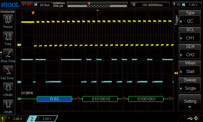
The oscilloscope supports serial protocol triggering and decoding for common embedded communication interfaces.
Supported protocols include:
- RS232 and UART
- I2C
- SPI
Protocol decoding displays interpreted communication data alongside the electrical waveform.
This helps users identify:
- Missing acknowledgements
- Incorrect data
- Timing errors
- Communication interruptions
- Voltage-level problems
- Electrical noise
- Physical-layer faults
Serial bus analysis should be described as option-dependent unless the applicable licence is confirmed as installed.
Parallel Bus Analysis
When the optional digital channels are enabled, the DS1104Z Plus supports parallel bus analysis.
This is useful for:
- Microcontroller data buses
- FPGA outputs
- Address and data lines
- Digital control systems
- Timing correlation between logic signals
- Mixed analogue and digital debugging
Parallel bus analysis requires the compatible RPL1116 logic probe.
Automatic Measurements
The oscilloscope supports automatic voltage, time, frequency and pulse measurements.
Typical measurements include:
- Maximum and minimum voltage
- Peak-to-peak voltage
- Top and base voltage
- Average voltage
- RMS voltage
- Frequency
- Period
- Rise and fall time
- Positive and negative pulse width
- Duty cycle
- Overshoot and preshoot
- Phase
- Delay
Measurement statistics can display current, average, minimum, maximum and standard deviation values over repeated acquisitions.
FFT and Waveform Mathematics
The DS1104Z Plus provides waveform mathematics and frequency-domain analysis.
Available functions include:
- Addition
- Subtraction
- Multiplication
- Division
- FFT
- Digital filtering
- Integration
- Differentiation
- Logical waveform operations
FFT analysis can be used for:
- Harmonic measurement
- Switching-frequency analysis
- Clock-spectrum observation
- Noise investigation
- EMI troubleshooting
- Detection of unwanted oscillations
- Amplifier and filter testing
The built-in FFT is suitable for general circuit analysis but does not replace a dedicated spectrum analyser for advanced RF measurements.
Mask and Pass/Fail Testing
Mask testing compares acquired waveforms against user-defined tolerance limits.
This function can support:
- Production-line validation
- Repetitive quality checks
- Signal-stability monitoring
- Component comparison
- Detection of waveform deviations
- Basic automated testing
The AUX output can provide trigger or pass/fail signalling to external equipment.
Frequency Counter
The oscilloscope includes a hardware frequency counter for repetitive signal measurements.
It can be used for:
- Clock-frequency verification
- Oscillator testing
- PWM frequency measurement
- Signal-generator checks
- General electronics troubleshooting
Display and User Interface
The DS1104Z Plus includes a 7-inch WVGA TFT colour display with 800 × 480 resolution.
Display features include:
- Up to 256 waveform intensity levels
- Dots and vector display modes
- Adjustable persistence
- Y-T, X-Y and Roll modes
- Multi-channel waveform display
- Dedicated controls for each analogue channel
- Search and navigation functions
- Decoded bus display
The interface can display four analogue waveforms, optional digital channels, measurements and bus information together.
Connectivity and Automated Testing
The DS1104Z Plus supports computer communication, network operation and automated test-system integration.
Available interfaces include:
- USB Host
- USB Device
- LAN
- LXI support
- AUX output
- Optional USB-to-GPIB connectivity
These interfaces support:
- Waveform transfer
- Screenshot storage
- Remote instrument control
- Automated measurements
- Production-test integration
- Laboratory data collection
HDMI output is not listed for the DS1104Z Plus and should not be added to the product page.
No Built-In Waveform Generator
The standard DS1104Z Plus does not include a waveform generator.
The DS1104Z-S Plus is the version that includes a built-in dual-channel 25 MHz function and arbitrary waveform generator.
Users requiring oscilloscope, logic-analysis and signal-generation functions in one instrument should select the “-S Plus” model.
Applications
The RIGOL DS1104Z Plus is suitable for:
- Embedded-system development
- Microcontroller debugging
- FPGA and CPLD testing
- Mixed-signal circuit analysis
- Analogue circuit testing
- Digital logic analysis
- Parallel bus debugging
- Serial protocol testing
- Power-supply analysis
- PWM testing
- Sensor and controller validation
- Electronic maintenance
- Production-line inspection
- Research and development
- Engineering education
- Service and repair applications
Why Buy from RevineTech?
RevineTech supplies professional test and measurement equipment for electronics development, industrial testing, research, education and production.
Technical product-selection support can include:
- DS1104Z Plus configuration
- RPL1116 logic-probe selection
- Memory-option verification
- Serial-decoding options
- Advanced trigger functions
- Waveform-recording activation
- Passive and differential probes
- High-voltage probes
- Current probes
- Calibration requirements
- Automated test integration
100 MHz Analogue Bandwidth
The DS1104Z Plus supports:
- Embedded controller signals
- Digital clock measurements
- PWM and pulse analysis
- Switching power-supply testing
- Sensor measurements
- Communication interface debugging
- General signal-integrity troubleshooting
Four Analogue Channels
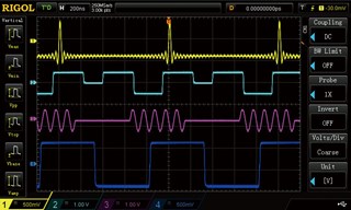
Four channels allow simultaneous measurement of:
- Clock, data and control signals
- Input and output waveforms
- Voltage and current
- Multiple power rails
- Sensor and controller signals
- Phase and timing relationships
Optional 16 Digital Channels
With the RPL1116 logic probe, the oscilloscope supports:
- Mixed-signal debugging
- Parallel bus analysis
- FPGA and microcontroller testing
- Time-correlated analogue and digital measurements
- Configurable digital thresholds
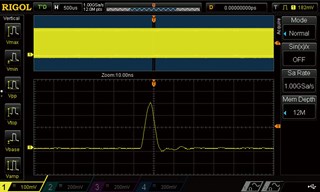
Up to 1 GSa/s Analogue Sampling
Sampling performance includes:
- 1 GSa/s with one analogue channel
- 500 MSa/s per channel with two analogue channels
- 250 MSa/s per channel with three or four analogue channels
Up to 1 GSa/s Digital Sampling
Digital sampling includes:
- 1 GSa/s with eight digital channels
- 500 MSa/s with all 16 digital channels
12 Mpts Standard Memory
Standard analogue memory provides:
- 12 Mpts with one channel
- 6 Mpts per channel with two channels
- 3 Mpts per channel with three or four channels
Optional 24 Mpts Memory
The memory option increases acquisition depth to:
- 24 Mpts with one channel
- 12 Mpts per channel with two channels
- 6 Mpts per channel with three or four channels
Up to 30,000 wfms/s Capture Rate
Fast acquisition helps locate:
- Glitches
- Runt pulses
- Timing errors
- Intermittent noise
- Signal instability
- Communication faults
Up to 60,000 Recorded Frames
Hardware waveform recording supports:
- Frame-by-frame playback
- Intermittent fault analysis
- Event comparison
- Long-duration monitoring
- Post-acquisition measurement
Serial Bus Analysis
Option-dependent protocol analysis supports:
- RS232/UART
- I2C
- SPI
FFT and Waveform Mathematics
Built-in analysis includes:
- FFT
- Arithmetic waveform operations
- Digital filtering
- Integration and differentiation
- Logical waveform operations
7-Inch Colour Display
The display provides:
- 800 × 480 resolution
- Up to 256 intensity levels
- Adjustable persistence
- Dots and vector modes
- Four-channel waveform display
- Optional analogue and digital display
USB and Network Connectivity
Interfaces include:
- USB Host
- USB Device
- LAN
- LXI
- AUX output
- Optional USB-GPIB