
.jpg)
.jpg)
Rigol DS7024
Precision You Can Trust
NABL-Accreditied Calibration | Available on Request
NABL-Accreditied Calibration | Available on Request
Rs. 498078.00
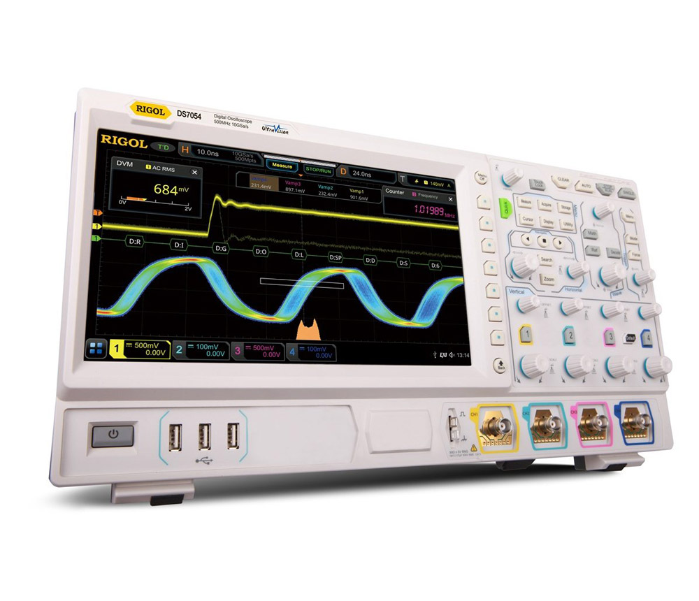
The RIGOL DS7024 is a 200 MHz, four-channel digital oscilloscope built for embedded design, power electronics, automotive testing, industrial troubleshooting and laboratory research. Powered by RIGOL’s Phoenix chipset and UltraVision II platform, it offers up to 10 GSa/s real-time sampling, 100 Mpts standard memory expandable to 500 Mpts, a capture rate of at least 600,000 waveforms per second and a responsive 10.1-inch multi-touch display..
RIGOL DS7024 Digital Oscilloscope Overview
The RIGOL DS7024 is a high-performance four-channel digital storage oscilloscope designed for engineers who need greater bandwidth, deep acquisition memory and advanced waveform-analysis capabilities without moving to a significantly higher-priced instrument class.
With 200 MHz analogue bandwidth, the DS7024 is suitable for faster embedded systems, switched-mode power supplies, motor drives, industrial electronics, automotive control units, communication interfaces and general research applications. It is part of the RIGOL MSO/DS7000 family and uses the proprietary Phoenix technology platform with UltraVision II architecture.
The oscilloscope includes:
- Four analogue input channels
- One external trigger input
- Up to 10 GSa/s real-time sampling
- 100 Mpts standard acquisition memory
- Optional memory expansion to 250 Mpts or 500 Mpts
- At least 600,000 waveform captures per second
- Hardware waveform recording and playback
- Advanced trigger and measurement functions
- Optional serial-bus analysis
- Optional power analysis
- A 10.1-inch capacitive touchscreen
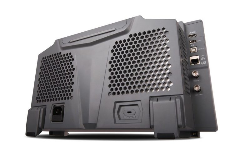
- LAN, USB, HDMI, GPIB and browser-based remote control
The DS7024 is the digital-storage version of the platform. Unlike the MSO7024, it does not support 16 digital logic channels or the optional two-channel arbitrary waveform generator. Serial-bus analysis is still possible through the four analogue input channels when the appropriate software option is installed.
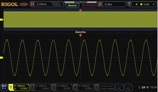
200 MHz Analogue Bandwidth
The DS7024 provides 200 MHz bandwidth across four analogue channels. This bandwidth is well suited to signals with faster edges and higher-frequency content than those typically handled by entry-level 70 MHz or 100 MHz oscilloscopes.
It can be used to measure and troubleshoot:
- Microcontroller and FPGA clock signals
- High-speed PWM waveforms
- Switching power converters
- Gate-driver signals
- Automotive control circuits
- Communication transceivers
- Sensor and actuator interfaces
- Industrial motor-control boards
- Oscillators and timing circuits
- Audio and mixed-signal electronics
- Power-supply start-up and shutdown sequences
- Digital pulses with fast rise and fall times
The bandwidth can later be upgraded electronically to 350 MHz or 500 MHz. The official upgrade licences for the DS7024 are DS7000-BW2T3 and DS7000-BW2T5.
Available bandwidth configurations
| Configuration | Analogue bandwidth |
|---|---|
| Standard DS7024 | 200 MHz |
| With DS7000-BW2T3 | 350 MHz |
| With DS7000-BW2T5 | 500 MHz |
This upgrade path allows laboratories to purchase the bandwidth required today while retaining the option to support faster projects in the future.
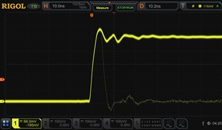
Four Analogue Channels and External Trigger
Four analogue input channels make it possible to view multiple circuit nodes simultaneously.
Typical four-channel measurements include:
- Input voltage, output voltage, gate drive and switching current
- Clock, data, enable and reset signals
- Three motor phases plus a control or feedback signal
- Multiple power rails during start-up
- Sensor excitation, response, reference and supply voltage
- PWM output, feedback, current-sense and fault signals
- Transmit, receive, clock and control lines
- Primary and secondary waveforms in power-conversion circuits
The separate external trigger input allows all four analogue channels to remain available for measurement while another signal controls acquisition timing.
Up to 10 GSa/s Real-Time Sampling
The DS7024 supports a maximum real-time sample rate of 10 GSa/s. Sampling resources are shared according to the number and grouping of active analogue channels.
| Active-channel arrangement | Maximum real-time sample rate |
|---|---|
| Single-channel operation | 10 GSa/s |
| Half-channel operation | 5 GSa/s |
| Four-channel operation | 2.5 GSa/s |
Channels 1 and 2 form one acquisition group, while channels 3 and 4 form another. In half-channel mode, one channel from each group may be enabled at up to 5 GSa/s per channel. When all four channels are active, the maximum sampling rate is 2.5 GSa/s per channel.
A high sampling rate helps preserve waveform detail when examining:
- Fast rising and falling edges
- Overshoot and undershoot
- Ringing
- Narrow glitches
- Pulse-width variation
- Timing relationships
- Switching transients
- Communication signal quality
- Clock instability
- Short-duration disturbances
At the maximum single-channel rate, the oscilloscope can place many sample points across rapid transitions, reducing the risk of missing important waveform behaviour.
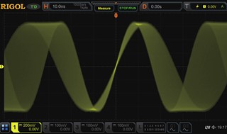
100 Mpts Standard Memory, Expandable to 500 Mpts
The RIGOL DS7024 includes 100 Mpts memory as standard. Optional licences increase the maximum memory depth to 250 Mpts or 500 Mpts.
Maximum analogue memory allocation with the 500 Mpts option is:
| Active-channel arrangement | Maximum memory depth |
|---|---|
| Single-channel operation | 500 Mpts |
| Half-channel operation | 250 Mpts |
| Four-channel operation | 125 Mpts |
The maximum memory is divided across active acquisition groups. Therefore, 500 Mpts should not be interpreted as 500 Mpts available independently on every channel.
Deep memory is valuable because it allows the oscilloscope to record a long time interval while maintaining a high sampling rate.
Engineers can capture:
- Complete power-up sequences
- Long serial communication transactions
- Motor acceleration cycles
- Intermittent failures
- Long PWM control sequences
- Multiple switching events
- Rare protection trips
- System resets
- Power interruptions
- Thermal or load-related signal changes
After acquisition, users can zoom into a small part of the waveform without losing the overall record.
High Waveform Capture Rate
The DS7024 offers a maximum waveform capture rate of at least 600,000 waveforms per second under the specified acquisition conditions.
A conventional oscilloscope may spend significant time processing and displaying each acquisition. During this dead time, an intermittent event can occur without being displayed. The DS7024’s fast acquisition architecture reduces this interval and improves the probability of observing rare faults.
This is particularly useful for detecting:
- Random glitches
- Missing pulses
- Noise bursts
- Timing violations
- Signal dropouts
- Metastable transitions
- Unstable switching waveforms
- Occasional communication errors
- Unexpected resets
- Irregular oscillator behaviour
The 256-level intensity-grading display indicates how frequently different waveform paths occur. Repetitive signal activity appears more prominently, while occasional events remain visually distinguishable.
Hardware Waveform Recording and Playback
The DS7024 supports hardware real-time waveform recording and playback of at least 450,000 frames in single-channel operation.
Segmented acquisition stores only waveform events that satisfy the configured trigger condition. This avoids using large amounts of memory to record inactive periods between relevant events.
Each recorded frame may be reviewed to analyse how a signal changes over time.
Typical uses include:
- Intermittent fault investigation
- Serial-bus error capture
- Power-converter protection trips
- Automotive ECU troubleshooting
- Motor-drive failure analysis
- Long-duration signal monitoring
- Production-line fault diagnosis
- Communication packet inspection
- Random noise investigation
Time tags help identify the relative timing of recorded events.
10.1-Inch Capacitive Multi-Touch Display
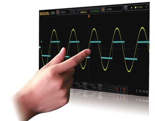
The DS7024 is equipped with a 10.1-inch capacitive colour touchscreen with gesture-enabled operation and a resolution of 1024 × 600 pixels.
Users can interact with waveforms through familiar touch gestures to:
- Move traces vertically or horizontally
- Adjust the time base
- Change channel scale
- Position cursors
- Set trigger levels
- Expand waveform regions
- Navigate long acquisitions
- Configure measurements
- Select menus and analysis functions
Physical knobs and front-panel buttons remain available for traditional oscilloscope operation. A USB mouse can also be used when preferred.
The large display provides sufficient space for viewing four analogue channels, measurements, decoded serial data, FFT traces and menu settings together.
Full-Memory Hardware Measurements
The DS7024 can calculate measurements across the complete acquisition memory rather than limiting calculations to the portion currently visible on screen.
This capability is particularly useful when:
- Capturing long records
- Comparing signals with substantially different frequencies
- Measuring burst signals
- Analysing start-up sequences
- Monitoring changing duty cycles
- Evaluating intermittent pulses
- Examining communication packets
- Measuring long-duration modulation
The instrument supports 41 automatic waveform parameters and can display up to ten measurement results simultaneously.
Automatic Waveform Measurements
The DS7024 provides a broad selection of automatic voltage, timing, pulse and statistical measurements.
Voltage measurements
- Maximum
- Minimum
- Peak-to-peak
- Amplitude
- Top
- Base
- Average
- RMS
- Overshoot
- Preshoot
Time measurements
- Frequency
- Period
- Rise time
- Fall time
- Positive pulse width
- Negative pulse width
- Positive duty cycle
- Negative duty cycle
- Delay
- Phase
Pulse and statistical measurements
- Positive pulse count
- Negative pulse count
- Rising-edge count
- Falling-edge count
- Area
- Cycle area
- Standard deviation
Measurement statistics help engineers evaluate changes across repeated acquisitions rather than relying on a single result.
Advanced Trigger System
The DS7024 includes multiple trigger modes for isolating specific waveform conditions.
Standard trigger types include:
- Edge
- Pulse
- Slope
- Video
- Pattern
- Duration
- Timeout
- Runt
- Window
- Delay
- Setup and hold
- Nth edge
Optional protocol trigger packages add support for:
- RS232 and UART
- I²C
- SPI
- CAN
- LIN
- FlexRay
- I²S
- MIL-STD-1553
These trigger modes allow engineers to capture events based on pulse shape, duration, voltage level, data pattern or serial-bus content rather than only a basic rising or falling edge.
Zone Triggering
Zone triggering provides a visual method for isolating unusual waveform behaviour.
The user draws a region directly on the touchscreen and instructs the oscilloscope to trigger when a waveform either enters or avoids that region.
This approach is helpful when an abnormal event is visually identifiable but difficult to express using conventional trigger parameters.
Zone triggering can help locate:
- Excessive overshoot
- Ringing
- Missing transitions
- Amplitude instability
- Timing jitter
- Unexpected waveform paths
- Abnormal pulse shapes
- Signal excursions outside an acceptable region
It can work with protocol decoding, waveform recording and pass/fail testing to support more complex debugging tasks.
Serial-Bus Trigger and Decode Options
The DS7024 supports optional serial-bus trigger and decode applications using its analogue input channels.
| Option | Protocol support |
|---|---|
| DS7000-COMP | RS232 and UART |
| DS7000-EMBD | I²C and SPI |
| DS7000-AUTO | CAN and LIN |
| DS7000-FLEX | FlexRay |
| DS7000-AUDIO | I²S |
| DS7000-AERO | MIL-STD-1553 |
Parallel-bus decoding is included as standard. The listed serial protocols require the corresponding software option or a compatible bundle.
Decoded data can be displayed alongside the electrical waveform, helping users relate protocol information to signal-integrity problems.
Typical applications include:
- Embedded-system debugging
- Automotive network analysis
- Industrial controller development
- Sensor-interface troubleshooting
- Audio communication testing
- Avionics system development
- Communication-board verification
Enhanced FFT Analysis
The DS7024 includes an enhanced Fast Fourier Transform function for frequency-domain signal analysis.
FFT analysis can help identify:
- Harmonic distortion
- Clock feed-through
- Switching noise
- Power-supply ripple
- Oscillator spurs
- Modulation components
- Resonance
- Electromagnetic interference sources
- Unwanted frequency components
The enhanced FFT supports:
- Record lengths up to 1 Mpts
- Up to 15 automatically identified peaks
- User-defined threshold settings
- Colour-grading display
- Multiple selectable window functions
Available FFT windows include:
- Rectangular
- Blackman-Harris
- Hanning
- Hamming
- Flattop
- Triangle
Colour FFT helps separate frequently occurring spectral components from intermittent frequency activity.
Waveform Mathematics and Digital Filtering
The DS7024 provides mathematical, logical and filtering operations for deriving additional information from acquired signals.
Arithmetic functions
- Addition
- Subtraction
- Multiplication
- Division
Calculus and advanced functions
- Integration
- Differentiation
- Base-10 logarithm
- Natural logarithm
- Exponential
- Square root
- Absolute value
- Linear transformation
Logic functions
- AND
- OR
- XOR
- NOT
Digital filters
- Low-pass
- High-pass
- Band-pass
- Band-stop
These functions can be used to compare input and output waveforms, calculate differential behaviour, remove unwanted frequency components and analyse signal relationships without exporting every record to a computer.
Waveform Histogram Analysis
Histogram analysis shows the distribution of waveform positions or measurement values over repeated acquisitions.
It is useful for evaluating:
- Timing jitter
- Amplitude variation
- Frequency stability
- Noise distribution
- Pulse-width consistency
- Duty-cycle variation
- Production tolerances
- Long-term drift
Histograms help identify outliers and gradual changes that may not be obvious from a single waveform acquisition.
Hardware Pass/Fail Testing
The DS7024 includes hardware pass/fail testing as a standard function.
A reference mask is created around an acceptable waveform. The oscilloscope then checks each acquisition against that mask and identifies signals that cross the permitted boundary.
The function is suitable for:
- Production testing
- Repetitive board inspection
- Component screening
- Power-supply validation
- Signal-quality monitoring
- Long-duration reliability testing
- Education and laboratory assessment
Depending on the configured procedure, the instrument can count failures, stop acquisition or activate an output when a failure occurs.
Integrated Digital Voltmeter
The built-in digital voltmeter provides convenient voltage measurements through the oscilloscope’s analogue input channels.
It may be used for:
- DC supply checks
- Bias-voltage verification
- RMS voltage measurements
- Average voltage monitoring
- Slowly varying signal analysis
- Circuit-stage comparison
This reduces the need to use a separate multimeter for routine voltage checks during waveform troubleshooting.
Frequency Counter and Totaliser
The DS7024 includes an integrated frequency counter and totaliser.
These functions support:
- Clock-frequency verification
- Oscillator testing
- Pulse counting
- Repetition-rate measurements
- Sensor-output evaluation
- Production-line inspection
The totaliser can count input events over a selected observation period.
Optional Power Analysis
The DS7000-PWR application adds built-in power-analysis functions.
It can support the evaluation of:
- Power quality
- Switching loss
- Conduction loss
- Current and voltage relationships
- Harmonic content
- Ripple
- Modulation
- Safe operating area
- Turn-on behaviour
- Turn-off behaviour
The RPA246 phase-difference correction jig is recommended for correcting voltage and current probe delay before performing switching-power measurements.
Remote Control and Automated Testing
The DS7024 supports Web Control, allowing authorised users to operate the oscilloscope through a browser over a network connection.
Remote operation is useful for:
- Automated test systems
- Production lines
- Environmental chambers
- Restricted-access laboratories
- Classroom demonstrations
- Shared engineering facilities
- Long-duration monitoring
The oscilloscope can also be controlled programmatically through supported interfaces for integration into automated test and measurement systems.
Connectivity
The DS7024 provides the following interfaces:
- USB 2.0 host
- USB 2.0 device
- LAN
- GPIB
- HDMI
- AUX output
- Probe compensation output
- Web Control
USB host connectivity supports external storage. USB device, LAN and GPIB connections support computer control and test-system integration. HDMI allows the oscilloscope display to be shown on a larger monitor.
Applications
Embedded-System Development
The DS7024 can be used to examine clocks, reset signals, PWM outputs, sensor interfaces, analogue signals and serial communication activity in microcontroller- and FPGA-based systems.
Power-Electronics Testing
Its four channels, 200 MHz bandwidth and optional power-analysis software make it suitable for evaluating switching power supplies, inverters, converters, gate drivers and power-control circuits.
Automotive Electronics
Optional CAN and LIN decoding supports analysis of automotive communication networks. Engineers can also measure sensors, actuators, ECU signals, ignition controls, motor drives and power systems.
Industrial Electronics
The oscilloscope is suitable for PLC-related electronics, motor controllers, variable-frequency drives, control boards, industrial sensors and automation systems.
Motor-Control Development
Four analogue channels allow engineers to view multiple phases, gate-drive signals, current feedback and control signals simultaneously.
Communication Interface Testing
Optional serial decoding and advanced triggering help troubleshoot UART, SPI, I²C, CAN, LIN, FlexRay and other supported interfaces.
Research and Education
The large touchscreen, deep memory and broad analysis functions make the DS7024 suitable for engineering colleges, universities, R&D centres and training laboratories.
Manufacturing and Quality Control
Hardware pass/fail testing, waveform recording and remote control support repetitive production testing and long-term signal monitoring.
General Electronics Troubleshooting
The DS7024 can help locate unstable supplies, distorted pulses, noise coupling, timing problems, intermittent resets and component-related failures.
Why Buy the RIGOL DS7024 from Revine Technologies?
Revine Technologies supplies professional test and measurement instruments for electronics design, research, manufacturing, automotive development, power electronics and educational laboratories in India.
Customers can receive support with:
- Selecting the appropriate oscilloscope bandwidth
- Choosing between DS7000 and MSO7000 models
- Planning future bandwidth upgrades
- Selecting acquisition-memory options
- Choosing passive, active, current and differential probes
- Identifying suitable serial-decoding packages
- Configuring power-analysis applications
- Integrating the oscilloscope into automated test systems
- Matching accessories to voltage, bandwidth and safety requirements
- Post-sales product and application coordination
Buying through an experienced measurement-equipment supplier helps ensure that the oscilloscope, software licences, probes and accessories are correctly matched to the intended application.
Phoenix Technology Platform
The proprietary RIGOL Phoenix platform integrates the analogue front end, acquisition system, triggering and waveform-processing functions.
Its architecture supports:
- Up to 10 GSa/s sampling
- Fast waveform capture
- Deep acquisition memory
- Reliable triggering
- Rapid scale switching
- Reduced overload-recovery time
- Consistent analogue-channel performance
UltraVision II Architecture
UltraVision II combines deep memory, fast acquisition, hardware measurements, waveform recording, advanced triggering, histogram analysis and a responsive touchscreen interface in one platform.

200 MHz Standard Bandwidth
The standard 200 MHz bandwidth gives the DS7024 greater capability for analysing fast switching signals, digital clocks and communication circuits than lower-bandwidth models.
Upgradeable to 350 MHz or 500 MHz
Electronic bandwidth licences allow the instrument to be upgraded without replacing the main hardware.
100 Mpts Standard Memory
The standard 100 Mpts memory supports long acquisitions at relatively high sampling rates. Optional licences expand the maximum capacity to 250 Mpts or 500 Mpts.
At Least 600,000 Waveforms per Second
The high acquisition rate improves the probability of observing intermittent and infrequent events.
Hardware Segmented Recording
At least 450,000 frames can be captured in single-channel operation, allowing efficient recording of relevant events separated by inactive periods.
Full-Memory Measurement
Measurements can be calculated over the complete acquired record instead of only the displayed section.
Large Multi-Touch Display
The 10.1-inch capacitive touchscreen supports direct waveform manipulation while retaining conventional physical controls.

256-Level Intensity Grading
Intensity grading visually represents waveform occurrence frequency, helping distinguish repetitive behaviour from occasional faults.
Advanced Triggering
Multiple standard and optional trigger modes allow precise isolation of pulse, timing, voltage and protocol conditions.
Enhanced FFT
Up to 1 Mpts FFT records, colour grading, six selectable windows and automatic peak search support detailed frequency-domain analysis.
Built-In Measurement Tools
The DS7024 integrates:
- Digital oscilloscope
- Protocol analysis through analogue channels
- Digital voltmeter
- Frequency counter
- Totaliser
- Optional power analysis
The logic-analyser and arbitrary-waveform-generator functions are available only on compatible MSO7000 models.