
.jpg)
.jpg)
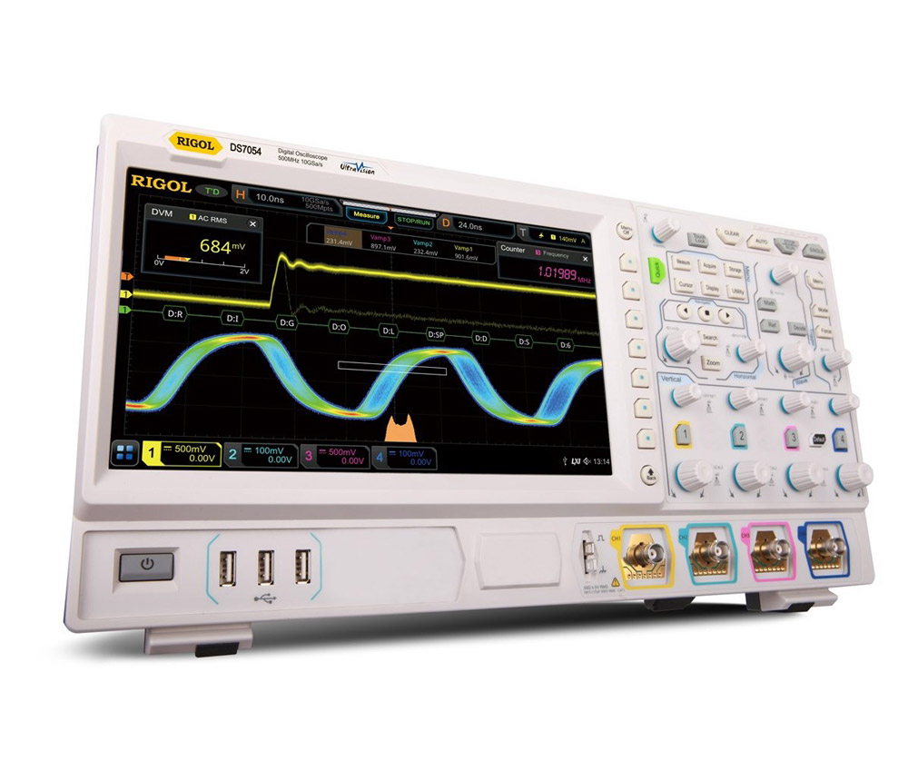
Rigol DS7054
Precision You Can Trust
NABL-Accreditied Calibration | Available on Request
NABL-Accreditied Calibration | Available on Request
Rs. 849423.00
The RIGOL DS7054 is a 500 MHz, four-channel digital oscilloscope engineered for high-speed embedded design, power electronics, automotive systems, industrial automation and advanced laboratory testing. Powered by RIGOL’s Phoenix chipset and UltraVision II platform, it delivers up to 10 GSa/s real-time sampling, 100 Mpts standard memory expandable to 500 Mpts, up to 600,000 waveform captures per second and a responsive 10.1-inch capacitive touchscreen..
RIGOL DS7054 Digital Oscilloscope Overview
The RIGOL DS7054 is the highest-bandwidth digital storage oscilloscope in the RIGOL DS7000 family. It combines four analogue input channels with 500 MHz bandwidth, deep acquisition memory, rapid waveform capture and advanced signal-analysis functions.
The instrument is designed for engineers working with fast digital clocks, high-speed embedded hardware, switching power converters, motor drives, automotive electronics, communication interfaces and complex industrial-control systems.
Built around RIGOL’s proprietary Phoenix chipset and UltraVision II architecture, the DS7054 provides:
- 500 MHz analogue bandwidth
- Four analogue input channels
- One external trigger input
- Up to 10 GSa/s real-time sampling
- 100 Mpts standard acquisition memory
- Optional memory expansion to 250 Mpts or 500 Mpts
- Up to 600,000 waveform captures per second
- Hardware waveform recording and playback
- Full-memory automatic measurements
- Advanced trigger functions
- Optional serial-protocol trigger and decode
- Optional power-analysis software
- Enhanced FFT and frequency-domain analysis
- Digital voltmeter
- Six-digit frequency counter and totaliser
- 10.1-inch capacitive multi-touch display
- USB, LAN, HDMI, GPIB and Web Control
The DS7054 is a four-channel digital oscilloscope. Unlike the corresponding MSO7054, it does not provide a 16-channel logic-analyser interface or arbitrary waveform-generator outputs. Serial communication signals can still be triggered and decoded through the analogue channels when the required software options are installed.
RIGOL identifies the DS7054 as the 500 MHz, four-channel model in the DS7000 series, with 10 GSa/s maximum sampling, 100 Mpts standard memory and a 600,000 waveforms-per-second capture rate.
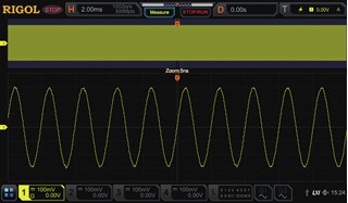
500 MHz Analogue Bandwidth
The DS7054 provides 500 MHz bandwidth on all four analogue input channels.
This bandwidth supports more accurate examination of fast transitions and higher-frequency signal content than 100 MHz, 200 MHz or 350 MHz models. It is especially valuable when the quality of a digital or switching waveform depends on harmonics well above its fundamental frequency.
The DS7054 can be used to analyse:
- High-speed microcontroller clocks
- Processor and FPGA timing signals
- Fast PWM outputs
- Gate-driver transitions
- Switching-node waveforms
- High-frequency DC-DC converters
- Automotive control electronics
- Industrial communication circuits
- Oscillator outputs
- High-speed sensor interfaces
- Fast pulse and timing circuits
- RF envelopes and modulation signals
- Power-converter control loops
- Communication transceiver waveforms
- Servo and motor-control electronics
The 500 MHz front end helps engineers evaluate waveform characteristics such as:
- Rise time
- Fall time
- Overshoot
- Undershoot
- Ringing
- Settling time
- Timing skew
- Pulse distortion
- Clock integrity
- Crosstalk
- Signal attenuation
- Transient disturbances
Unlike lower-bandwidth models in the family, the DS7054 is supplied at the maximum DS7000 bandwidth and does not require a bandwidth-upgrade licence.
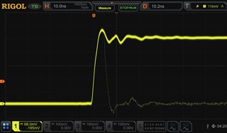
Four Analogue Input Channels
The DS7054 provides four analogue channels for examining multiple circuit points during the same acquisition.
Four-channel visibility is useful for analysing cause-and-effect relationships across a system. Engineers can observe signals before, during and after a fault without repeating the test under different measurement conditions.
Typical channel combinations include:
- Input voltage, input current, switching voltage and output voltage
- Clock, data, enable and reset
- Gate drive, drain voltage, current and control signal
- Three motor phases and a feedback signal
- Primary voltage, primary current, secondary voltage and secondary current
- Multiple power rails during system start-up
- Sensor output, reference, supply and control signal
- PWM command, feedback, current sense and fault output
- Transmit, receive, clock and control lines
- Encoder channels, motor current and drive output
A separate external trigger input allows the oscilloscope to trigger from an additional signal while preserving all four analogue channels for measurement.
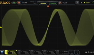
Up to 10 GSa/s Real-Time Sampling
The RIGOL DS7054 supports a maximum real-time sample rate of 10 GSa/s.
The acquisition resources are shared according to the active-channel arrangement.
| Active-channel configuration | Maximum real-time sample rate |
|---|---|
| One analogue channel active | 10 GSa/s |
| Half-channel operation | 5 GSa/s |
| All four analogue channels active | 2.5 GSa/s |
Channels 1 and 2 share one acquisition group, while channels 3 and 4 share the second group. When one channel from each group is active, each active channel can operate at up to 5 GSa/s. When all four analogue channels are enabled, the maximum rate is 2.5 GSa/s per channel.
At the maximum sampling rate, a 500 MHz signal can be sampled at up to twenty times its frequency. This gives engineers greater visibility into waveform details that might be missed at lower sample rates. RIGOL specifically highlights the 10 GSa/s sample rate as a means of observing short transient artefacts on high-speed embedded signals.
High sampling performance is important when investigating:
- Narrow glitches
- Rapid switching transitions
- Short-duration overshoot
- Ringing
- Clock jitter
- Pulse-width variation
- Timing errors
- Metastable events
- Communication disturbances
- Intermittent noise
- Fast protection responses
100 Mpts Standard Memory
The DS7054 includes 100 Mpts of acquisition memory as standard.
Optional memory licences can expand the maximum available record length to:
- 250 Mpts
- 500 Mpts
The deep-memory system allows engineers to capture a long time interval while maintaining a high sampling rate.
With the 500 Mpts option installed, memory is allocated according to the active-channel configuration.
| Active-channel configuration | Maximum memory depth |
|---|---|
| One analogue channel active | 500 Mpts |
| Half-channel operation | 250 Mpts |
| All four analogue channels active | 125 Mpts |
The 500 Mpts value represents the maximum acquisition-system capacity. It should not be interpreted as 500 Mpts independently available on every active analogue channel.
Deep memory is particularly useful for recording:
- Complete power-up sequences
- Long communication transactions
- Motor acceleration and braking cycles
- Intermittent failures
- Long PWM modulation sequences
- System resets
- Protection trips
- Burst-mode converter operation
- Extended control-loop behaviour
- Thermal or load-dependent faults
- Infrequent protocol errors
- Long production-test cycles
Users can capture the complete event and then zoom into a short interval without losing the surrounding system context.
RIGOL states that the DS7000 platform supports 100 Mpts as standard and up to 500 Mpts optionally, together with waveform search, navigation and recording tools for handling long acquisitions.
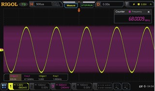
Up to 600,000 Waveforms per Second
The DS7054 supports a waveform capture rate of up to 600,000 waveforms per second under specified operating conditions.
Waveform capture rate indicates how frequently the oscilloscope can acquire and display a new waveform. A higher rate reduces the dead time between acquisitions and improves the probability of observing rare events.
The DS7054 can help reveal:
- Random glitches
- Missing pulses
- Timing violations
- Signal dropouts
- Noise bursts
- Metastable transitions
- Unstable clock behaviour
- Irregular switching edges
- Communication errors
- Occasional protection trips
- Unexpected resets
- Intermittent amplitude changes
The instrument’s high capture rate can remain available while using many of its measurement and analysis functions, supporting detailed troubleshooting without significantly reducing waveform visibility.
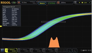
Intensity-Graded Waveform Display
The DS7054 uses intensity and colour grading to show how frequently different waveform paths occur.
Frequently repeated waveform regions appear with stronger intensity, while low-probability events are displayed differently. This makes it easier to distinguish normal repetitive activity from rare abnormalities.
Intensity grading can help identify:
- Intermittent noise
- Changing edge positions
- Timing jitter
- Multiple operating states
- Sporadic pulse distortion
- Unstable amplitude
- Modulation behaviour
- Rare signal excursions
- Ringing that occurs only under specific conditions
The probability-based display is particularly useful when several waveform behaviours overlap.
Hardware Waveform Recording and Playback
The DS7054 supports hardware waveform recording and playback of up to approximately 450,000 frames in single-channel operation.
Instead of storing long periods in which no meaningful activity occurs, segmented acquisition records only events that satisfy the selected trigger condition.
This makes more efficient use of acquisition memory and allows engineers to analyse large numbers of individual events.
Applications include:
- Intermittent circuit-fault capture
- Serial communication error analysis
- Power-converter protection trips
- Automotive ECU troubleshooting
- Motor-drive shutdown investigation
- Random noise monitoring
- Oscillator instability analysis
- Production-line failure recording
- Repeated start-up testing
- Long-duration reliability studies
Stored frames can be reviewed individually or played back as a sequence to show how signal behaviour changes over time.
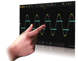
10.1-Inch Capacitive Multi-Touch Display
The RIGOL DS7054 includes a 10.1-inch capacitive colour touchscreen with 1024 × 600-pixel resolution.
The large display provides sufficient working area for viewing:
- Four analogue waveforms
- Measurement results
- Measurement statistics
- Serial-bus decoding
- FFT traces
- Cursors
- Trigger settings
- Histograms
- Search markers
- Analysis menus
Touch gestures allow users to:
- Move waveforms horizontally and vertically
- Change the time base
- Adjust channel sensitivity
- Set trigger levels
- Position cursors
- Zoom into waveform regions
- Navigate long records
- Configure measurements
- Select analysis functions
The instrument also retains physical knobs and buttons for conventional oscilloscope operation. Mouse control is supported for users who prefer a desktop-style interface.
RIGOL describes the DS7000 user interface as supporting touch, mouse, physical controls, browser operation and remote programming.
Full-Memory Hardware Measurements
The DS7054 can calculate waveform measurements across the entire acquisition record instead of using only the portion visible on the display.
This is valuable when working with:
- Long waveform records
- Burst signals
- Start-up and shutdown sequences
- Modulated signals
- Different-frequency signals
- Intermittent pulses
- Changing duty cycles
- Long serial transactions
- Motor-control cycles
- Power-conversion sequences
Full-memory measurement helps prevent important waveform information outside the visible display region from being excluded from calculated results.
The oscilloscope supports 41 automatic waveform parameters and can display up to ten measurement results simultaneously.
Automatic Waveform Measurements
The DS7054 provides voltage, timing, pulse, phase and statistical measurements.
Voltage measurements
- Maximum
- Minimum
- Peak-to-peak
- Amplitude
- Top
- Base
- Average
- RMS
- Overshoot
- Preshoot
Timing measurements
- Frequency
- Period
- Rise time
- Fall time
- Positive pulse width
- Negative pulse width
- Positive duty cycle
- Negative duty cycle
- Delay
- Phase
Pulse and statistical measurements
- Positive pulse count
- Negative pulse count
- Rising-edge count
- Falling-edge count
- Area
- Cycle area
- Standard deviation
Measurement statistics provide minimum, maximum, average and variation information across repeated acquisitions, helping engineers determine whether a circuit is stable over time.
Advanced Trigger System
The DS7054 includes an extensive trigger system for isolating specific waveform conditions.
Standard trigger modes include:
- Edge
- Pulse
- Slope
- Video
- Pattern
- Duration
- Timeout
- Runt
- Window
- Delay
- Setup and hold
- Nth edge
- Zone
These modes allow engineers to trigger according to:
- Voltage level
- Edge direction
- Pulse width
- Rise or fall rate
- Logic pattern
- Duration
- Timing relationship
- Abnormal pulse shape
- Signal location within a voltage window
Optional protocol-trigger packages add support for:
- RS232 and UART
- I²C
- SPI
- CAN
- LIN
- FlexRay
- I²S
- MIL-STD-1553
Zone Triggering
Zone triggering provides a graphical way to isolate unusual signal behaviour.
The operator draws one or more regions on the touchscreen and configures the oscilloscope to trigger when the waveform either:
- Enters a selected zone
- Avoids a selected zone
This approach is useful when a fault is visually recognisable but difficult to describe through conventional numeric trigger settings.
Zone triggering can help locate:
- Excessive overshoot
- Ringing
- Missing transitions
- Unexpected waveform paths
- Amplitude instability
- Timing jitter
- Pulse distortion
- Signal excursions
- Incomplete settling
- Irregular modulation
It can be combined with waveform recording, protocol analysis and pass/fail testing.
Optional Serial-Bus Trigger and Decode
The DS7054 can trigger on and decode common serial communication protocols through its analogue channels.
Up to four serial buses can be decoded simultaneously, depending on channel availability and installed options. Decoded traffic can also be presented in an event table for easier examination.
| Software option | Supported protocols |
|---|---|
| DS7000-COMP | RS232 and UART |
| DS7000-EMBD | I²C and SPI |
| DS7000-AUTO | CAN and LIN |
| DS7000-FLEX | FlexRay |
| DS7000-AUDIO | I²S |
| DS7000-AERO | MIL-STD-1553 |
Decoded information can be displayed alongside the electrical waveform. This allows engineers to correlate protocol data with physical-layer issues such as:
- Noise
- Slow rise or fall times
- Incorrect voltage levels
- Ringing
- Missing acknowledgements
- Timing errors
- Invalid data
- Bus contention
- Communication dropouts
Typical protocol-analysis applications include:
- Embedded-system debugging
- Automotive network testing
- Industrial controller development
- Sensor-bus troubleshooting
- Audio-interface validation
- Avionics communication testing
Parallel-bus analysis is also supported by the platform, although the DS7054 does not provide the 16 digital channels available on the MSO7054.
Enhanced FFT Analysis
The DS7054 includes an enhanced Fast Fourier Transform function for viewing acquired signals in the frequency domain.
FFT analysis helps identify:
- Harmonics
- Switching noise
- Power-supply ripple
- Clock feed-through
- Oscillator spurs
- Modulation components
- Resonance
- Electromagnetic interference sources
- Unwanted frequency content
- Hopping or intermittent frequency components
The FFT system supports:
- Record lengths up to 1 Mpts
- Up to 15 automatically detected peaks
- User-defined thresholds
- Offset threshold settings
- Probability-based colour grading
- Multiple window functions
Available FFT windows include:
- Rectangular
- Blackman-Harris
- Hanning
- Hamming
- Flattop
- Triangle
RIGOL’s colour FFT applies probability-based colourisation to highlight intermittent and hopping frequency components in a manner similar to real-time spectral visualisation.
Mathematical Waveform Operations
The DS7054 provides multiple mathematical functions for analysing relationships between acquired waveforms.
Arithmetic functions
- Addition
- Subtraction
- Multiplication
- Division
Calculus and advanced functions
- Integration
- Differentiation
- Base-10 logarithm
- Natural logarithm
- Exponential
- Square root
- Absolute value
- Linear transformation
Logic functions
- AND
- OR
- XOR
- NOT
These functions can be used to:
- Compare input and output signals
- Calculate differential waveforms
- Derive instantaneous power
- Analyse phase relationships
- Evaluate control-loop behaviour
- Remove common signal components
- Generate calculated traces
Digital Filtering
Built-in digital filters include:
- Low-pass
- High-pass
- Band-pass
- Band-stop
Digital filtering helps isolate the frequency content relevant to a measurement and suppress unwanted noise or interference.
Waveform Histogram Analysis
Histogram analysis shows the statistical distribution of waveform positions or measurement values across repeated acquisitions.
It is useful for evaluating:
- Timing jitter
- Amplitude variation
- Noise distribution
- Pulse-width stability
- Frequency variation
- Duty-cycle consistency
- Production tolerance
- Long-term drift
- Clock stability
- Repeated switching behaviour
Histograms provide a clearer view of signal variation than a single waveform or measurement result.
Hardware Pass/Fail Testing
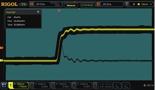
The DS7054 includes hardware-based pass/fail testing for repetitive waveform inspection.
A mask is defined around an acceptable waveform. Each subsequent acquisition is compared against that mask.
The oscilloscope can be configured to:
- Count failures
- Stop acquisition
- Save failed waveforms
- Generate an output signal
- Continue monitoring
- Record abnormal events
Pass/fail testing is suitable for:
- Production-line inspection
- PCB verification
- Component screening
- Power-supply quality testing
- Signal-integrity checks
- Reliability monitoring
- Educational laboratory assessment
Built-In Digital Voltmeter
The integrated digital voltmeter provides convenient voltage readings through the analogue input channels.
It can be used for:
- DC supply verification
- Bias-voltage measurement
- Average voltage monitoring
- RMS voltage measurement
- Slowly varying signal analysis
- Comparison of circuit stages
This function can reduce the need to switch repeatedly between an oscilloscope and a separate digital multimeter during troubleshooting.
Six-Digit Frequency Counter and Totaliser
The DS7054 includes an integrated six-digit frequency counter and totaliser.
Applications include:
- Clock-frequency verification
- Oscillator testing
- Pulse counting
- Sensor-output analysis
- Repetition-rate measurement
- Timing-system testing
- Production inspection
The totaliser counts signal events over a selected measurement interval.
Optional Power Analysis
The DS7000-PWR option adds dedicated power-analysis functions for power-electronics development.
It can support the analysis of:
- Input power quality
- Switching loss
- Conduction loss
- Harmonic content
- Output ripple
- Modulation
- Turn-on behaviour
- Turn-off behaviour
- Safe operating area
- Voltage and current relationships
Power-analysis applications include:
- AC-DC power supplies
- DC-DC converters
- Inverters
- Motor drives
- Power-factor-correction circuits
- Renewable-energy converters
- Industrial power systems
The RPA246 phase-difference correction jig can be used to compensate for timing differences between voltage and current probes before switching-loss calculations.
Remote Operation and Automated Testing
The DS7054 supports browser-based Web Control through its LAN interface.
Authorised users can remotely:
- View the oscilloscope display
- Configure channels
- Adjust the time base
- Set triggers
- Start and stop acquisitions
- Perform measurements
- Save results
Remote operation is useful in:
- Automated test systems
- Production lines
- Restricted-access laboratories
- Environmental chambers
- Shared engineering facilities
- Educational demonstrations
- Long-duration monitoring
Programming interfaces allow the oscilloscope to be integrated into automated test sequences and computer-controlled measurement systems.
Connectivity
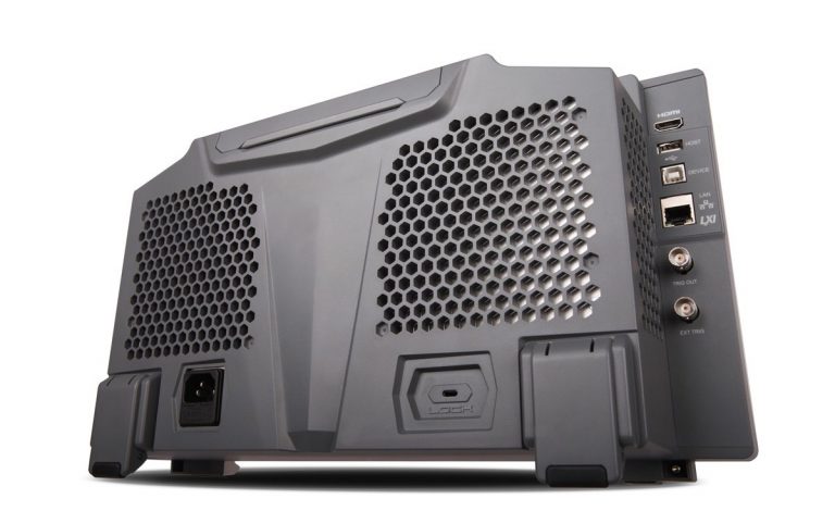
The DS7054 offers the following interfaces:
- USB 2.0 host
- USB 2.0 device
- LAN
- GPIB
- HDMI
- AUX output
- Probe compensation output
- Web Control
USB host connectivity supports external storage. USB device, LAN and GPIB interfaces allow computer control and automated-system integration. HDMI can mirror the display on a larger external monitor.
Applications
High-Speed Embedded-System Development
The DS7054 is suitable for debugging processors, microcontrollers, FPGAs and embedded communication systems.
It can be used to examine:
- High-frequency clocks
- Reset and enable signals
- Memory-control signals
- PWM outputs
- Sensor interfaces
- Communication traffic
- Power sequencing
- High-speed digital transitions
Signal-Integrity Testing
The 500 MHz bandwidth supports examination of:
- Overshoot
- Undershoot
- Ringing
- Clock distortion
- Timing skew
- Crosstalk
- Pulse deformation
- Slow settling
- Amplitude loss
- Reflections
Power-Electronics Development
The four analogue channels and optional power-analysis functions make the DS7054 suitable for:
- Switching power supplies
- DC-DC converters
- AC-DC converters
- Inverters
- Gate-driver circuits
- Power-factor-correction systems
- Motor drives
- Industrial power converters
Automotive Electronics
The oscilloscope can be used to test:
- Electronic control units
- Sensors
- Actuators
- Ignition electronics
- Electric-motor drives
- Battery-management circuits
- CAN and LIN communication
- Power-conversion systems
Industrial Control and Automation
Applications include:
- PLC-associated electronics
- Variable-frequency drives
- Servo drives
- Robotics
- Factory automation equipment
- Industrial sensors
- Control boards
- Machine-monitoring systems
Motor-Control Development
Four channels allow simultaneous observation of:
- Gate-drive signals
- Phase voltages
- Phase currents
- Encoder outputs
- Current feedback
- PWM commands
- Fault signals
Communication Interface Testing
Optional serial decoding supports embedded, industrial, automotive, audio and avionics communication systems.
Research and Education
The DS7054 is suitable for universities, engineering institutes, R&D laboratories and advanced technical-training facilities requiring high bandwidth and deep acquisition memory.
Manufacturing and Quality Control
The instrument’s pass/fail testing, recording capability and remote-control support can be used for:
- Repetitive production inspection
- Component screening
- PCB validation
- Failure analysis
- Reliability monitoring
- Automated end-of-line testing
Why Buy the RIGOL DS7054 from Revine Technologies?
Revine Technologies supplies test and measurement solutions for electronics design, research, manufacturing, automotive development, power engineering and educational laboratories across India.
Customers can receive assistance with:
- Selecting the appropriate oscilloscope series
- Comparing DS7054 and MSO7054 configurations
- Choosing acquisition-memory upgrades
- Selecting passive and active probes
- Choosing differential and current probes
- Configuring serial-decode options
- Selecting power-analysis software
- Matching probes to bandwidth and voltage requirements
- Planning automated-test integration
- Choosing rack-mount and communication accessories
- Post-sales product and application support
Purchasing through Revine Technologies helps ensure that the oscilloscope, probes, software licences and accessories are matched correctly to the intended measurement requirements.
500 MHz Maximum DS7000 Bandwidth
The DS7054 is supplied with the highest analogue bandwidth available in the DS7000 family.
Its 500 MHz front end provides greater visibility into fast edge behaviour and high-frequency waveform content.
Phoenix Chipset
RIGOL’s proprietary Phoenix chipset integrates important analogue front-end, acquisition, triggering and processing functions.
The platform enables:
- 10 GSa/s maximum sampling
- Rapid waveform capture
- Deep acquisition memory
- Fast signal processing
- Stable triggering
- Reliable channel performance
- Responsive user-interface operation
UltraVision II Architecture
UltraVision II combines:
- Deep memory
- Fast acquisition
- Hardware measurements
- Intensity grading
- Advanced triggering
- Waveform recording
- Serial-protocol analysis
- Enhanced FFT
- Search and navigation
- Touchscreen control
100 Mpts Standard Memory
The standard memory supports lengthy acquisitions while retaining high sampling rates.
Up to 500 Mpts Optional Memory
Memory licences allow users to expand the acquisition capacity to 250 Mpts or 500 Mpts.
Up to 600,000 Waveforms per Second
Fast acquisition improves the likelihood of observing intermittent faults and low-probability waveform events.
Hardware Segmented Recording
Up to approximately 450,000 frames can be stored in single-channel operation, allowing relevant events to be captured without recording long inactive intervals.
Full-Memory Measurements
Automatic measurements can be calculated over the complete acquired record rather than only the waveform section shown on screen.
10.1-Inch Multi-Touch Display
The capacitive display supports direct waveform manipulation while retaining dedicated physical controls.
Intensity and Colour Grading
Probability-based display grading helps users distinguish repetitive waveform behaviour from rare signal abnormalities.
Zone Triggering
Graphical trigger zones make visually identifiable waveform faults easier to capture.
Enhanced FFT
The frequency-domain analysis system offers:
- Up to 1 Mpts FFT records
- Six window functions
- Probability colour grading
- Automatic peak search
- Up to 15 displayed peaks
Optional Protocol Analysis
Supported serial protocols include:
- RS232/UART
- I²C
- SPI
- CAN
- LIN
- FlexRay
- I²S
- MIL-STD-1553
Integrated Measurement Functions
Depending on the installed software options, the DS7054 combines:
- Digital oscilloscope
- Serial-protocol analyser
- Digital voltmeter
- Six-digit frequency counter
- Totaliser
- Power analyser
The DS7054 does not support the 16-channel logic-analyser or arbitrary waveform-generator hardware available on the corresponding MSO7054.