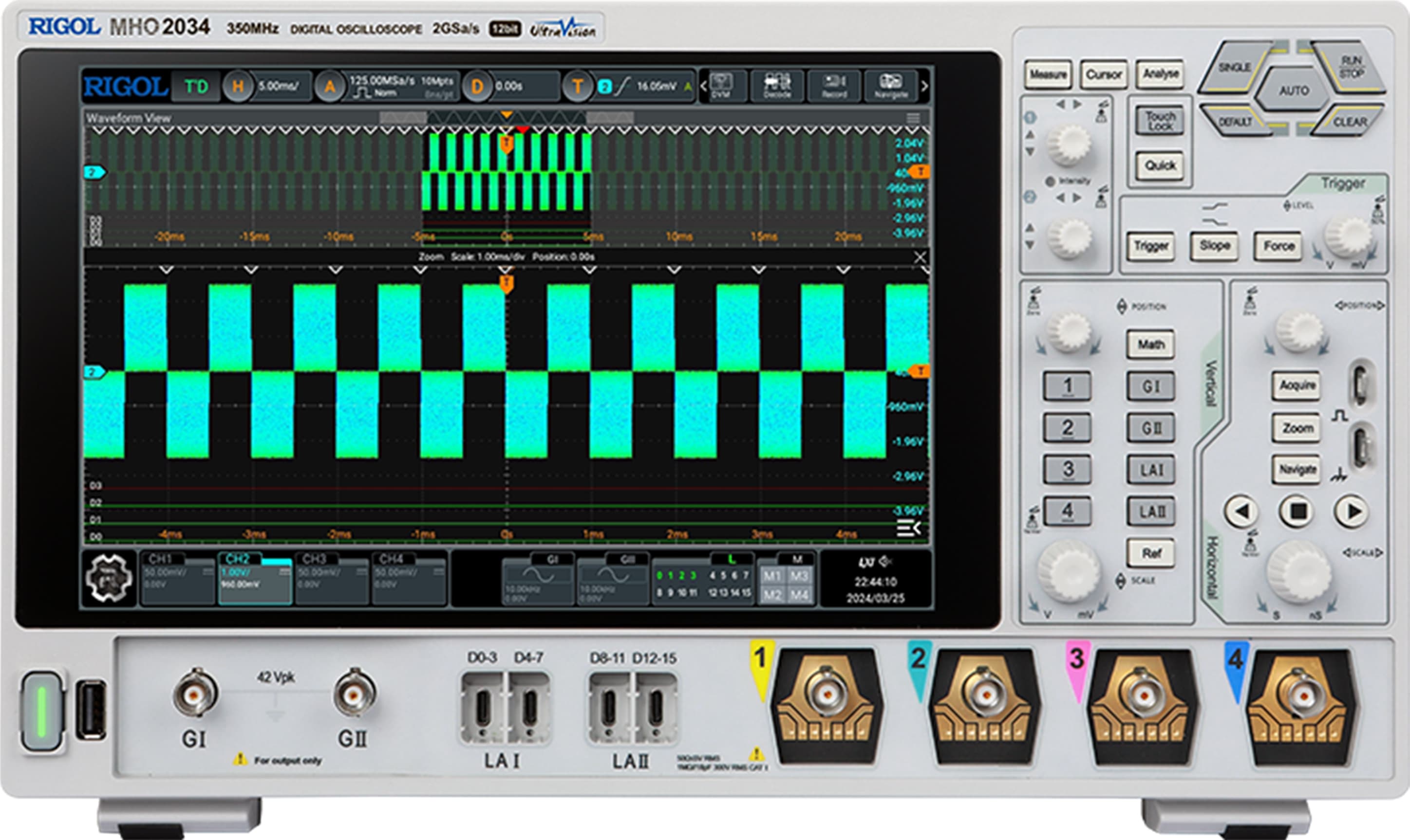
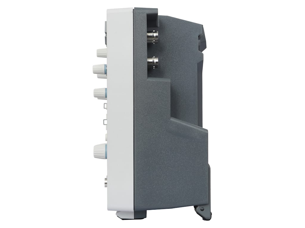
The RIGOL MHO2034 Mixed-Signal Oscilloscope is the 350 MHz model in the RIGOL MHO2000 Series. It is developed for engineers, technicians, electronics manufacturers, research laboratories and educational institutions that need detailed analogue measurements together with digital logic and protocol analysis.
Built on RIGOL’s Centaurus high-resolution technology platform, the MHO2034 combines four analogue channels, 16 digital channels, deep acquisition memory and advanced analysis functions within one expandable instrument.
Its 12-bit analogue-to-digital converter provides 4,096 vertical quantisation levels. This gives the oscilloscope 16 times more vertical levels than a conventional 8-bit oscilloscope, helping users identify small voltage variations, low-amplitude noise, power-supply ripple and other fine waveform details.
350 MHz Analogue Bandwidth
The MHO2034 provides 350 MHz analogue bandwidth across four input channels.
This bandwidth supports measurements involving:
- Embedded processors and microcontrollers
- FPGA-based systems
- Digital clock signals
- Switching power converters
- Industrial control electronics
- Automotive communication buses
- High-speed analogue circuits
- Communication interfaces
- Sensor and actuator systems
The specified typical rise time is approximately 1.4 ns at 50 Ω, allowing the oscilloscope to capture relatively fast waveform transitions and timing behaviour.
Four Analogue Channels and One External Trigger
The MHO2034 includes:
- Four analogue input channels
- One external trigger input
- 16 digital channels with a compatible PLA3204 logic probe
The four analogue inputs allow engineers to acquire multiple related signals within the same time-correlated measurement.
Typical applications include:
- Comparing circuit input and output
- Measuring clock, data, enable and reset signals
- Monitoring multiple power rails
- Examining gate, drain and current waveforms
- Testing multi-phase power systems
- Comparing sensor and actuator signals
The separate external trigger input allows the oscilloscope to trigger from an additional signal without occupying an analogue measurement channel.
Mixed-Signal Analysis
The MHO2034 platform includes 16 digital-channel capability. A compatible RIGOL PLA3204 logic analysis probe is required to connect digital signals.
Mixed-signal analysis allows analogue and digital waveforms to be displayed on the same time base.
This is useful for:
- Microcontroller debugging
- FPGA validation
- Parallel bus analysis
- ADC and DAC testing
- Embedded control systems
- Digital power applications
- Logic timing analysis
- Correlating analogue events with digital activity
RIGOL describes the digital channels as a standard platform capability, while the logic probe is supplied separately.
2 GSa/s Sampling on All Channels
The MHO2034 provides a maximum real-time sampling rate of 2 GSa/s on all four analogue channels.
This independent per-channel performance allows engineers to capture four related signals without reducing the maximum 2 GSa/s sampling rate when all channels are active.
High-speed sampling supports detailed analysis of:
- Fast signal edges
- Short-duration pulses
- Clock signals
- Serial communication
- Switching transitions
- Overshoot and ringing
- Timing errors
- Intermittent glitches
The combination of 350 MHz bandwidth and 2 GSa/s per channel provides approximately five times oversampling at the oscilloscope’s rated bandwidth.
Deep Acquisition Memory
The MHO2034 provides:
- Up to 500 Mpts in half-channel operation
- Up to 250 Mpts when all four analogue channels are active
Half-channel operation refers to an acquisition configuration in which one channel from each analogue channel pair is enabled.
Deep memory allows engineers to capture longer signal sequences while maintaining a high sample rate.
It is especially useful for:
- Long serial bus acquisitions
- Embedded-software debugging
- Power-up sequence analysis
- Intermittent fault investigation
- Communication packet analysis
- Multi-cycle measurements
- Extended waveform monitoring
- Detailed waveform zooming
The memory specification should therefore be written as up to 500 Mpts, rather than 500 Mpts simultaneously available on each of the four channels.
Fast Waveform Capture
The MHO2034 provides:
- Up to 200,000 wfms/s in Vector mode
- Up to 1,000,000 wfms/s in fast recording mode
A faster waveform capture rate reduces acquisition dead time and increases the probability of finding uncommon signal events.
This capability helps identify:
- Rare glitches
- Runt pulses
- Signal dropouts
- Timing violations
- Intermittent noise
- Unstable clock signals
- Abnormal waveform transitions
- Occasional protocol errors
Fast recording is particularly useful when a fault appears only occasionally and cannot be reproduced during every acquisition.
12-Bit Vertical Resolution
The 12-bit ADC provides 4,096 amplitude levels.
This helps improve visibility during:
- Power-supply ripple measurement
- Sensor output analysis
- Low-level analogue testing
- Audio signal measurement
- Medical electronics testing
- Power integrity analysis
- Precision voltage measurement
- Small-signal troubleshooting
Compared with an 8-bit oscilloscope, the MHO2034 provides finer voltage quantisation and better separation of closely spaced amplitude values.
Up to 16-Bit High Resolution Mode
High Resolution acquisition processing can increase effective vertical resolution up to 16 bits.
This mode can help:
- Reduce visible random noise
- Improve low-frequency measurement clarity
- Reveal small waveform variations
- Improve low-level amplitude analysis
- Support precision power measurements
The available bandwidth and sample-rate performance can decrease when higher-resolution modes are selected.
Low-Noise Signal Measurement
The MHO2034 provides vertical sensitivity down to 100 μV/div.
This supports measurements involving:
- Power-rail ripple
- Low-level sensor signals
- Reference voltages
- Audio waveforms
- Analogue control signals
- Power-supply noise
- Low-amplitude embedded signals
The actual measurement noise depends on probe selection, bandwidth, vertical scale, input impedance, acquisition mode and environmental conditions.
Serial Bus Triggering and Decoding
The MHO2034 supports serial bus triggering and decoding for embedded, automotive, audio and aerospace systems.
Standard embedded protocol capabilities include:
Additional protocol options include:
- CAN
- CAN FD
- LIN
- FlexRay
- SENT
- I2S
- MIL-STD-1553B
Decoded protocol information is displayed together with the electrical waveform, helping engineers identify:
- Incorrect addresses
- Invalid data
- Missing acknowledgements
- Timing problems
- Frame errors
- Communication interruptions
- Intermittent bus faults
Automotive, FlexRay, audio and aerospace analysis functions may require separate software licences.
Advanced Trigger Functions
The MHO2034 provides multiple trigger modes for capturing specific signal conditions.
Available trigger functions include:
- Edge
- Pulse width
- Interval
- Timeout
- Video
- Pattern
- Duration
- Runt
- Window
- Delay
- Setup and hold
- Nth edge
- Zone trigger
- Serial bus trigger
Zone triggering allows users to draw an area directly on the waveform display and acquire waveforms that enter or avoid that region.
This visual triggering method can simplify the detection of glitches, abnormal transitions and infrequent waveform conditions.
Automatic Measurements and Analysis
The oscilloscope provides a broad set of measurement and analysis tools.
Available functions include:
- Voltage measurements
- Frequency and period measurements
- Rise and fall time
- Pulse width
- Duty cycle
- Overshoot and preshoot
- Channel delay
- Phase measurement
- Measurement statistics
- Cursor measurements
- FFT frequency analysis
- Waveform mathematics
- Histogram analysis
- Mask testing
- Pass/fail testing
- Search and navigation
- Hardware waveform recording
- Digital voltmeter
- Frequency counter
These functions allow engineers to move from waveform capture to detailed analysis without exporting every acquisition to separate software.
Search and Navigation
Search and navigation tools help users examine long memory records and locate specific waveform events.
Users can search according to conditions such as:
- Edge transitions
- Pulse widths
- Runt pulses
- Logic patterns
- Serial bus events
- Timing violations
Search results can be marked within the acquisition record, allowing engineers to move directly between abnormal events.
Optional Dual-Channel 50 MHz AWG
The optional MHO2000-AWG adds a built-in dual-channel waveform generator.
AWG specifications include:
- Two output channels
- Maximum frequency up to 50 MHz
- 1 GSa/s sampling
- 16-bit vertical resolution
- 200 ps two-channel synchronisation accuracy
Available waveforms include:
- Sine
- Square
- Pulse
- Ramp
- Noise
- DC
- Sinc
- Exponential rise
- Exponential fall
- ECG
- Gaussian
- Lorentz
- Haversine
The built-in generator can be used for:
- Circuit stimulation
- Filter testing
- Amplifier evaluation
- Sensor simulation
- Clock generation
- Embedded-system debugging
- Frequency-response testing
The AWG is an optional software-enabled capability.
Bode Plot Analysis
With the optional built-in AWG, the MHO2034 supports Bode plot measurements.
Bode analysis can be used for:
- Filter frequency-response testing
- Amplifier gain analysis
- Power-supply control-loop testing
- Phase-response measurement
- Crossover-frequency identification
- Gain-margin evaluation
- Phase-margin evaluation
Suitable probes, test leads and an injection transformer may be required depending on the device under test.
Optional Power Analysis
The optional power-analysis application supports testing of power supplies, converters and switching semiconductor devices.
Typical measurements include:
- Power quality
- Switching loss
- Conduction loss
- Harmonic analysis
- Inrush current
- Output ripple
- Safe operating area
- Converter efficiency
- Modulation analysis
- Power-device behaviour
High-voltage differential probes and current probes should be selected according to the maximum voltage, current, bandwidth and common-mode requirements.
Battery-Powered Operation
The MHO2000 platform supports portable operation with a compatible optional battery holder and battery configuration.
Battery operation can be useful for:
- Field diagnostics
- Automotive servicing
- Measurements away from an AC outlet
- Portable engineering work
- Isolated test locations
- Temporary industrial installations
Battery compatibility, operating duration and regional availability should be confirmed before ordering.
10.1-Inch HD Touchscreen
The MHO2034 includes a 10.1-inch capacitive multi-touch display with a resolution of 1280 × 800 pixels.
The display supports:
- Waveform dragging
- Horizontal and vertical zooming
- Cursor positioning
- Menu navigation
- Measurement selection
- Protocol decode display
- Digital-channel viewing
- Multi-window analysis
- Search-result navigation
Physical knobs and buttons are also provided for conventional oscilloscope control.
Connectivity and Remote Operation
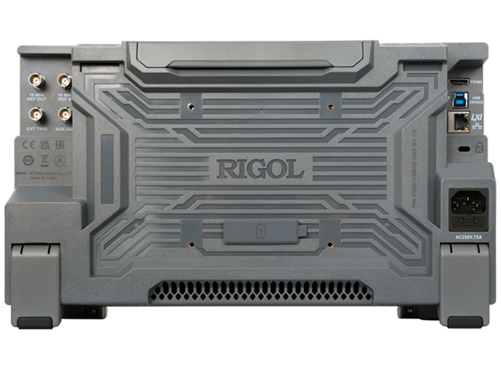
Available interfaces include:
- USB Host
- USB Device
- LAN
- LXI
- HDMI
- AUX output
- External trigger input
- Probe compensation output
These interfaces support:
- USB storage
- PC communication
- Remote programming
- Automated test integration
- External display connection
- Screenshot transfer
- Waveform export
- Network-based operation
-
Applications:
The RIGOL MHO2034 is suitable for:
- Embedded-system development
- Microcontroller debugging
- FPGA validation
- Mixed-signal analysis
- High-speed analogue testing
- Digital timing analysis
- Serial bus decoding
- Automotive electronics
- CAN and CAN FD testing
- Power electronics
- Power-supply development
- Industrial control systems
- Sensor signal analysis
- Medical electronics
- Audio electronics
- Research and development
- Production validation
- Educational laboratories
- Field diagnostics
- Service and repair laboratories
-
Why Buy from Revine Tech:
Revine Tech supplies oscilloscopes, logic probes, signal-generation options and electronic test equipment for industrial, research and educational applications.
Technical selection support can include:
- Oscilloscope bandwidth assessment
- Analogue and digital channel requirements
- PLA3204 logic probe selection
- Memory configuration
- Embedded protocol analysis
- Automotive bus analysis
- Power-analysis software
- Optional waveform generator
- Bode plot accessories
- Passive and active probe selection
- High-voltage differential probes
- Current probes
- Battery-operation requirements
- Remote-control integration
- Calibration and documentation
The final RIGOL MHO2034 price depends on the selected software options, logic probe, waveform generator, battery accessories, measurement probes and calibration requirements.