Home All Rigol Oscilloscopes Rigol MHO900-AFG100
All Rigol Oscilloscopes

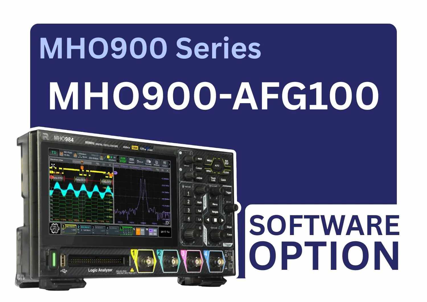
Rigol MHO900-AFG100

Now includes NABL Calibration Certificate.

The RIGOL MHO900-AFG100 is a licensed 100 MHz Function/Arbitrary Waveform Generator option for compatible MHO900 Series oscilloscopes. It activates dual-channel output with 1 GSa/s sampling, 16-bit vertical resolution, sine, square, ramp, noise, DC, arbitrary and built-in waveforms. It also supports AM, FM and PM modulation, phase adjustment and Bode plot testing for circuit response analysis..

  • Detail
  • Special Features
  • Specification

The RIGOL MHO900-AFG100 Function/Arbitrary Waveform Generator Option expands a compatible RIGOL MHO900 Series oscilloscope with integrated dual-channel signal-generation capability. It is a licensed function upgrade rather than a separate benchtop waveform generator.

Once activated, the option allows engineers to generate controlled test signals while measuring circuit behaviour on the same oscilloscope platform. This combination is useful for electronics development, embedded-system testing, amplifier analysis, filter testing, control-loop evaluation, frequency-response measurements and educational laboratory work.

The AFG100 option provides a maximum sine-wave output frequency of 100 MHz, a 1 GSa/s sample rate and 16-bit vertical resolution. It supports standard, arbitrary, built-in and user-defined waveforms for a broad range of simulation and test requirements.


Supported Output Waveforms

The waveform generator supports the following basic waveforms:

  • Sine
  • Square
  • Ramp
  • DC
  • White noise
  • Arbitrary waveform

It also includes built-in waveforms such as:

  • Sinc
  • Exponential rise
  • Exponential fall
  • ECG1
  • Gaussian
  • Lorentz
  • Haversine

User-defined waveforms are supported, allowing engineers to reproduce specialised test signals that are not available in the standard waveform library.


Waveform-Specific Frequency Ranges

The 100 MHz rating applies to sine-wave generation. The maximum output frequency varies according to the selected waveform:

  • Sine: 2 mHz to 100 MHz
  • Square: 2 mHz to 20 MHz
  • Ramp: 2 mHz to 2 MHz
  • Arbitrary waveform: 2 mHz to 20 MHz
  • Built-in waveform: 2 mHz to 20 MHz
  • White noise: greater than 100 MHz typical -3 dB bandwidth

This waveform-specific information should be considered when selecting the option for high-frequency testing.


Arbitrary Waveform Generation

The RIGOL MHO900-AFG100 supports arbitrary waveform generation with a waveform length of 16 kpts. Arbitrary waveform files can be imported in CSV format, making it possible to generate customised signals for simulation, fault reproduction and device-response testing.


Typical arbitrary waveform applications include:

  • Sensor-output simulation
  • Communication pulse testing
  • Power-supply disturbance testing
  • Control-signal simulation
  • Reproduction of recorded signal patterns
  • Custom waveform development
  • Device stress and response testing
  •  

Frequency-Response and Bode Plot Testing

The AFG100 option supports the MHO900 Series Bode plot function. The oscilloscope uses the integrated waveform generator to excite the device under test while measuring its amplitude and phase response.


The supported Bode plot configuration includes:

  • Start frequency from 10 Hz to 3 MHz
  • Stop frequency from 100 Hz to 30 MHz
  • 10 to 100 measurement points per decade
  • Output amplitude from 20 mV to 10 V
  •  

This capability is useful for analysing:

  • Amplifiers
  • Active and passive filters
  • Feedback networks
  • Power-supply control loops
  • Audio circuits
  • Sensor-conditioning circuits
  • Frequency-dependent components
  • Educational electronics experiments

The Bode plot stop frequency is limited to 30 MHz even though the AFG sine-wave output can reach 100 MHz.


Modulation Capabilities

The option supports internal AM, FM and PM modulation. Available modulating waveforms include sine, square, triangle, upward ramp, downward ramp and noise. Supported carrier waveforms include sine, square and ramp.


The modulation functions are useful for:

  • Communication-circuit testing
  • Modulated-signal simulation
  • Receiver and demodulator evaluation
  • Educational experiments
  • Frequency and phase response testing
  • Fault-condition simulation
  •  

Suitable Applications

The RIGOL MHO900-AFG100 is suitable for:

  • Electronic circuit design and debugging
  • Embedded-system testing
  • Frequency-response analysis
  • Bode plot measurement
  • Filter and amplifier testing
  • Power-supply loop analysis
  • Sensor and actuator simulation
  • Communication circuit testing
  • Automotive electronics development
  • Research and development laboratories
  • Production testing
  • Educational engineering laboratories
  • Device characterisation
  • Custom waveform simulation
  •  

Installation and Activation

The MHO900-AFG100 is a licensed software function option for compatible MHO900 Series oscilloscopes. RIGOL’s ordering process requires the serial number of the target instrument so that the option can be activated for the correct oscilloscope.

The option can also be obtained as part of the MHO900-BND function and application bundle, which includes AFG100 and selected protocol-analysis options.


Why Buy from RevineTech?

RevineTech provides test and measurement equipment, configuration guidance and application-based product selection for engineering laboratories, electronics manufacturers, educational institutions and industrial testing teams.


Support can include:

  • MHO900 Series compatibility confirmation
  • AFG100 licence selection
  • Option activation guidance
  • Probe and cable selection
  • Bode plot configuration guidance
  • Test-system integration support
  • Product quotation and availability information


Dual-Channel Waveform Output

The AFG100 activates two waveform-generator channels within a compatible MHO900 Series oscilloscope. Dual-channel generation allows users to create two test signals for applications involving stimulus comparison, phase relationships, multi-input circuits and synchronised signal testing.


100 MHz Maximum Sine-Wave Frequency

The option provides sine-wave generation from 2 mHz to 100 MHz. This broad frequency range supports low-frequency control-circuit testing as well as higher-frequency electronics and communication applications.


1 GSa/s Sample Rate

The integrated generator operates at a 1 GSa/s sample rate, supporting detailed waveform generation and reproduction of customised signals.


16-Bit Vertical Resolution

The 16-bit vertical resolution provides fine output-level control when generating low-amplitude signals, modulated signals and detailed arbitrary waveforms.


Adjustable Output Amplitude

Output amplitude depends on signal frequency and termination.

For a 50 Ω load:

  • 1 mVpp to 10 Vpp at frequencies up to 50 MHz
  • 1 mVpp to 5 Vpp at frequencies above 50 MHz and up to 100 MHz

For a high-impedance load:

  • 2 mVpp to 20 Vpp at frequencies up to 50 MHz
  • 2 mVpp to 10 Vpp at frequencies above 50 MHz and up to 100 MHz

Therefore, the maximum 10 Vpp into 50 Ω and 20 Vpp into high impedance apply only at frequencies up to 50 MHz.


Phase Adjustment

Sine, square and ramp waveforms support phase adjustment from 0° to 360° with 0.01° resolution. This is useful for phase-sensitive testing, multi-channel circuit analysis and timing comparison.


16 kpts Arbitrary Waveform Length

The arbitrary waveform generator supports a waveform length of 16 kpts and CSV file import. This enables engineers to create, save and reproduce custom signal patterns.


AM, FM and PM Modulation

Supported internal modulation types include:

  • Amplitude modulation
  • Frequency modulation
  • Phase modulation

The modulation frequency range is 2 mHz to 1 MHz. AM depth is adjustable from 0% to 120%, while PM phase shift can be set from 0° to 360°.

Adjustable Square-Wave Duty Cycle

Square-wave duty cycle is adjustable from 1% to 99%, supporting pulse-width testing, clock simulation and digital circuit evaluation.


Adjustable Ramp Symmetry

Ramp-wave symmetry can be adjusted from 0% to 100%, allowing users to generate triangular, rising-ramp and falling-ramp signal shapes.


Low-Distortion Sine Output

Typical sine-wave performance includes:

  • Total harmonic distortion below 0.1% from 10 Hz to 20 kHz at 1 Vpp
  • Harmonic distortion below -55 dBc from 10 Hz to below 10 MHz at 0 dBm
  • Phase noise below -110 dBc/Hz at 20 MHz with a 10 kHz offset

These typical specifications support signal-quality testing and precise circuit stimulation.


Integrated Bode Plot Support

The option provides the signal source required for Bode plot testing directly from the oscilloscope. This reduces the need for a separate waveform generator in many frequency-response measurement applications.

Product Name RIGOL MHO900-AFG100
Product Type Function/Arbitrary Waveform Generator licence option
Compatible Series RIGOL MHO900 Series oscilloscopes
Output Channels 2
Output Mode Normal dual-channel output
Maximum Frequency 100 MHz
Sample Rate 1 GSa/s
Vertical Resolution 16-bit
Basic Waveforms Sine, square, ramp, DC, noise and arbitrary
Built-In Waveforms Sinc, exponential rise, exponential fall, ECG1, Gaussian, Lorentz and Haversine
User-Defined Waveforms Supported
Arbitrary Waveform Length 16 kpts
Arbitrary File Type CSV
Phase Range 0° to 360°
Phase Resolution 0.01°
Modulation Types AM, FM and PM
Output Impedance 50 Ω ±1%, typical
Bode Plot Support Supported
Option Installation Licence activation for the target MHO900 instrument


Frequency Specifications

Waveform Frequency Range
Sine 2 mHz to 100 MHz
Square 2 mHz to 20 MHz
Ramp 2 mHz to 2 MHz
Arbitrary 2 mHz to 20 MHz
Built-In Waveforms 2 mHz to 20 MHz
White Noise Bandwidth Greater than 100 MHz typical -3 dB bandwidth
Frequency Resolution 0.1 Hz or 10 digits, whichever is greater
Frequency Accuracy ±1.5 ppm, plus ±1 ppm/year at 10 MHz


Output Amplitude Specifications

Load and Frequency Output Range
50 Ω, up to 50 MHz 1 mVpp to 10 Vpp
50 Ω, above 50 MHz to 100 MHz 1 mVpp to 5 Vpp
High impedance, up to 50 MHz 2 mVpp to 20 Vpp
High impedance, above 50 MHz to 100 MHz 2 mVpp to 10 Vpp
Amplitude Resolution 0.1 mVpp or 3 digits, whichever is smaller
Amplitude Accuracy ±1.5% of setting plus 5 mVpp, at 1 kHz sine and 0 V offset


DC Offset Specifications

Specification Details
50 Ω Load ±5 Vpk, AC plus DC
High-Impedance Load ±10 Vpk, AC plus DC
Offset Resolution 1 mV or 4 digits
Output Impedance 50 Ω ±1%, typical


Square-Wave Specifications

Specification Details
Frequency Range 2 mHz to 20 MHz
Rise/Fall Time Less than 10 ns typical at amplitude up to 2 Vpp into 50 Ω
Overshoot Less than 5% typical
Duty Cycle 1% to 99%, adjustable
Jitter 500 ps RMS typical
Phase 0° to 360°, 0.01° resolution


Ramp-Wave Specifications

Specification Details
Frequency Range 2 mHz to 2 MHz
Symmetry 0% to 100%
Linearity 1% or less of peak output under specified typical test conditions
Phase 0° to 360°, 0.01° resolution


Modulation Specifications

Modulation Details
AM Internal source, 0% to 120% modulation depth
FM Internal source with adjustable frequency deviation
PM Internal source, 0° to 360° phase shift
Modulating Waveforms Sine, square, triangle, upward ramp, downward ramp and noise
Carrier Waveforms Sine, square and ramp
Modulation Frequency 2 mHz to 1 MHz


Bode Plot Specifications

Specification Details
Start Frequency 10 Hz to 3 MHz
Stop Frequency 100 Hz to 30 MHz
Points per Decade 10 to 100
Output Amplitude 20 mV to 10 V
Function Requirement MHO900-AFG100 or supported AFG option