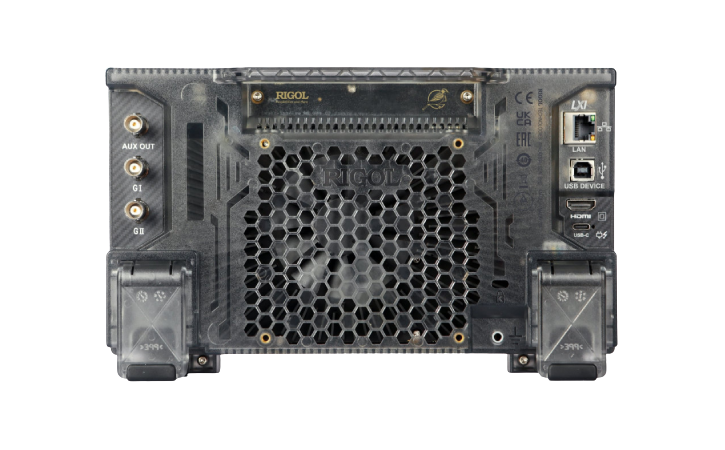
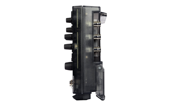
The RIGOL MHO954 Mixed-Signal Oscilloscope is a 500 MHz model in the MHO900 Series. It is designed for engineers, technicians, research laboratories, educational institutions and electronics manufacturers that need high-resolution analogue acquisition together with digital logic and serial bus analysis.
Its 12-bit analogue-to-digital converter provides 4,096 vertical quantisation levels. This is 16 times the number of levels provided by a conventional 8-bit oscilloscope, helping users observe small voltage changes, ripple, noise, overshoot and other fine waveform details more clearly.
The MHO954 combines:
- 500 MHz maximum analogue bandwidth
- Four analogue input channels
- 12-bit hardware vertical resolution
- Up to 16-bit High Resolution processing
- Up to 4 GSa/s real-time sampling
- 100 Mpts standard maximum memory
- Optional memory up to 500 Mpts
- Up to 1,000,000 wfms/s waveform capture
- 16 digital channels with the PLA2216 probe
- Standard embedded and automotive bus decoding
- Optional dual-channel 50 MHz or 100 MHz waveform generator
- 7-inch capacitive multi-touch display
Its compact chassis makes it suitable for crowded engineering benches, portable test stations, educational laboratories and field-support environments.
500 MHz Analogue Bandwidth
The MHO954 provides up to 500 MHz analogue bandwidth when one or two analogue channels are enabled.
When three or four analogue channels are enabled, maximum bandwidth reduces to 400 MHz.
| Active Analogue Channels |
Maximum Bandwidth |
| One channel |
500 MHz |
| Two channels |
500 MHz |
| Three or four channels |
400 MHz |
The 500 MHz bandwidth supports applications such as:
- Embedded processor debugging
- FPGA and CPLD testing
- High-speed clock analysis
- Communication interface testing
- Fast pulse measurements
- Automotive electronics
- Switching power converters
- Signal-integrity troubleshooting
- Semiconductor circuit evaluation
The rated bandwidth applies under the conditions defined in the official RIGOL specifications, including the selected input path and acquisition configuration.
Four Analogue Channels
The four analogue inputs allow engineers to capture and compare multiple signals on the same time base.
Typical four-channel measurements include:
- Clock, data, enable and reset lines
- Circuit input and output signals
- Multiple power rails
- MOSFET gate and switching-node waveforms
- Sensor and actuator signals
- Transmit and receive communication lines
- Multi-phase converter signals
- Analogue and digital control relationships
The MHO954 supports both 1 MΩ and 50 Ω input impedance, allowing conventional passive-probe measurements as well as direct 50 Ω signal connections.
12-Bit Vertical Resolution
The MHO954 uses a 12-bit ADC that provides 4,096 vertical levels.
This high-resolution acquisition system helps reveal waveform details during:
- Power-supply ripple measurement
- Low-level sensor testing
- Reference-voltage analysis
- Audio circuit debugging
- Noise investigation
- Power-integrity measurements
- Analogue control-loop testing
- Small-signal analysis
Compared with an 8-bit oscilloscope, the additional vertical levels improve the separation of closely spaced amplitudes and make small variations on larger signals easier to observe.
Up to 16-Bit High Resolution Mode
High Resolution processing can increase effective vertical resolution up to 16 bits.
This acquisition mode uses signal processing to reduce random noise and improve the visibility of low-level waveform details.
It is useful for:
- Low-frequency precision measurements
- Power-rail ripple analysis
- Sensor output testing
- Reference-voltage measurement
- Audio and analogue circuit analysis
- Noise-sensitive measurements
Maximum bandwidth and sample rate may be reduced when higher-resolution modes are selected.
Channel-Dependent Sample Rate
The maximum real-time sample rate depends on the number of active analogue channels.
| Active Analogue Channels |
Maximum Sample Rate |
| One channel |
4 GSa/s |
| Two channels |
2 GSa/s |
| Three or four channels |
1 GSa/s |
The product should therefore be described as providing up to 4 GSa/s, rather than 4 GSa/s simultaneously across all four channels.
High-speed sampling helps preserve waveform detail when measuring:
- Fast edges
- Narrow pulses
- Digital clocks
- Serial communication signals
- Switching transitions
- Overshoot and ringing
- Timing errors
- Intermittent glitches
-
Deep Acquisition Memory
The MHO954 includes up to 100 Mpts standard acquisition memory. An optional upgrade expands the maximum depth to 500 Mpts.
Memory is allocated according to the number of active analogue channels.
| Active Analogue Channels |
Standard Memory |
Optional Maximum Memory |
| One channel |
100 Mpts |
500 Mpts |
| Two channels |
50 Mpts |
250 Mpts |
| Three or four channels |
25 Mpts |
125 Mpts |
Deep memory allows engineers to capture long signal sequences while retaining enough sample detail for waveform expansion and analysis.
Typical applications include:
- Long serial bus acquisitions
- Communication packet analysis
- Power-up sequence testing
- Embedded-software debugging
- Intermittent fault investigation
- Extended waveform monitoring
- Multi-cycle timing measurements
- Detailed waveform zooming
The product specification should state 100 Mpts standard and up to 500 Mpts optional, while clearly explaining the channel-dependent allocation.
Fast Waveform Capture
The MHO954 provides:
- Up to 30,000 wfms/s in Vector acquisition mode
- Up to 1,000,000 wfms/s in fast recording mode
The maximum fast recording rate applies under specific acquisition settings defined by RIGOL.
A high waveform capture rate reduces acquisition dead time and increases the probability of finding uncommon events such as:
- Rare glitches
- Runt pulses
- Signal dropouts
- Timing violations
- Unstable clock behaviour
- Intermittent noise
- Abnormal waveform transitions
- Occasional protocol errors
The digital phosphor display uses 256-level intensity grading to help distinguish frequently occurring waveform activity from rare events.
Hardware Waveform Recording
The oscilloscope supports hardware waveform recording and playback of up to 500,000 frames.
Recorded waveforms can be reviewed frame by frame or replayed as a sequence.
This allows users to:
- Capture intermittent events
- Review individual acquisitions
- Compare normal and abnormal signals
- Decode previously recorded communication activity
- Investigate faults after extended testing
- Monitor circuits without continuous supervision
Peak Detect acquisition can identify narrow glitches under supported acquisition conditions.
Mixed-Signal Capability
The MHO954 supports 16 digital channels when used with the optional RIGOL PLA2216 logic analyser probe.
The digital channels are displayed on the same time base as the analogue channels, allowing engineers to correlate electrical waveform behaviour with digital logic activity.
Mixed-signal operation is useful for:
- Microcontroller debugging
- FPGA validation
- Parallel bus testing
- ADC and DAC analysis
- Embedded control-system development
- State-machine troubleshooting
- Digital power testing
- Analogue-to-digital timing correlation
The oscilloscope contains the mixed-signal capability, but the PLA2216 probe must be purchased separately.
Standard Serial Bus Decoding
The MHO954 includes standard protocol decoding for:
- Parallel bus
- RS232/UART
- I²C
- SPI
- LIN
- CAN
Up to four protocol decoders can be displayed simultaneously.
Protocol analysis allows decoded packets and electrical waveforms to be viewed together. This helps engineers identify:
- Incorrect addresses
- Invalid data
- Missing acknowledgements
- Frame errors
- Timing problems
- Communication interruptions
- Intermittent bus faults
Analogue channels or digital channels can be selected as protocol sources, depending on the interface and connected logic probe.
Optional Protocol Analysis
Additional protocol-analysis licences are available for:
- CAN FD
- FlexRay
- I²S
- MIL-STD-1553B
These options extend the oscilloscope for automotive, audio and aerospace applications.
| Optional Protocol |
Typical Application |
| CAN FD |
Automotive networks and electronic control units |
| FlexRay |
Deterministic automotive communication |
| I²S |
Digital audio interface testing |
| MIL-STD-1553B |
Aerospace and defence communication systems |
Protocol licences should be selected according to the buses used in the device under test.
Advanced Trigger Functions
The MHO954 provides multiple trigger types for isolating specific waveform conditions.
Available trigger functions include:
- Edge
- Pulse width
- Slope
- Video
- Pattern
- Duration
- Timeout
- Runt
- Window
- Delay
- Setup and hold
- Nth edge
- Serial bus triggering
These trigger modes help engineers capture a specific fault rather than manually reviewing large numbers of normal acquisitions.
Waveform Search and Navigation
Search and navigation tools help locate events within long acquisition records.
Users can search for conditions such as:
- Edge transitions
- Pulse-width violations
- Runt pulses
- Logic patterns
- Timing events
- Serial bus conditions
Matching events can be marked inside the waveform record, allowing users to move directly between points of interest.
Automatic Measurements and Analysis
The MHO954 provides a broad collection of measurement and waveform-analysis tools.
Available functions include:
- Voltage measurements
- Frequency and period
- Rise and fall time
- Pulse width
- Duty cycle
- Phase measurement
- Channel delay
- Measurement statistics
- Cursor measurements
- FFT frequency analysis
- Waveform mathematics
- Digital filtering
- Histogram analysis
- Mask testing
- Pass/fail testing
- Digital voltmeter
- Frequency counter
- Waveform recording and playback
These tools support both general circuit debugging and repetitive validation workflows.
Optional Dual-Channel Waveform Generator
The MHO954 supports two optional integrated function and arbitrary waveform generator configurations:
- MHO900-AFG50: Two channels with sine output up to 50 MHz
- MHO900-AFG100: Two channels with sine output up to 100 MHz
The generator options provide:
- Two independent outputs
- 1 GSa/s sampling
- 16-bit vertical resolution
- 16 kpts arbitrary waveform length
- Built-in and user-defined waveforms
- Sine, square, ramp, noise and DC output
- Arbitrary waveform generation
The maximum output frequency depends on the selected waveform type.
The integrated generator can be used for:
- Circuit stimulation
- Filter testing
- Amplifier analysis
- Sensor simulation
- Clock generation
- Embedded-system development
- Frequency-response testing
-
Bode Plot Analysis
When an optional AFG is installed, the MHO954 can perform Bode plot measurements.
Bode analysis supports:
- Gain response
- Phase response
- Frequency-response testing
- Filter characterisation
- Amplifier analysis
- Power-supply control-loop testing
- Crossover-frequency measurement
- Gain-margin evaluation
- Phase-margin evaluation
The supported Bode sweep extends from 10 Hz to a maximum stop frequency of 30 MHz.
Appropriate probes and an injection transformer may be required for power-supply loop-response measurements.
Low-Level Signal Measurement
Vertical sensitivity depends on the selected input impedance.
| Input Impedance |
Vertical Sensitivity |
| 50 Ω |
200 μV/div to 1 V/div |
| 1 MΩ |
1 mV/div to 10 V/div |
The low-range settings support measurements such as:
- Power-rail ripple
- Sensor outputs
- Reference-voltage noise
- Audio signals
- Low-amplitude control signals
- Power-integrity disturbances
Probe attenuation, grounding, bandwidth limitation and environmental noise must be considered when measuring very small signals.
7-Inch Multi-Touch Display
The MHO954 includes a 7-inch capacitive multi-touch display with:
- 1024 × 600 resolution
- 16:9 aspect ratio
- 256-level intensity grading
- Gesture-based waveform navigation
- Touch-controlled measurements
- Flex knob operation
The compact display and enclosure make the oscilloscope suitable for space-limited laboratories and portable test applications.
Connectivity and Remote Control
Standard interfaces include:
- USB Host
- USB Device
- 100 Mbps LAN
- HDMI output
- Web Control
- SCPI remote programming
These interfaces support:
- USB storage
- PC communication
- Automated test integration
- External monitor connection
- Screenshot and waveform transfer
- Browser-based remote operation
- Network control
Wireless adapter compatibility may vary by region and supplied configuration.
Applications
The RIGOL MHO954 is suitable for:
- Embedded-system development
- Microcontroller debugging
- FPGA and CPLD testing
- Mixed-signal analysis
- High-speed digital circuit testing
- Serial protocol debugging
- CAN and CAN FD analysis
- Automotive electronics
- Industrial control systems
- Switching power-supply testing
- Power electronics
- Sensor signal measurement
- Communication circuit development
- Audio electronics
- Research and development
- Production validation
- Educational laboratories
- Service and repair
- Field testing
-
Why Buy from Revine Tech
Revine Tech supplies RIGOL oscilloscopes, logic probes, protocol options, waveform-generator upgrades and measurement accessories for professional electronic testing.
Technical selection support can include:
- Bandwidth and model selection
- Analogue and digital channel requirements
- PLA2216 logic probe selection
- Memory-depth upgrades
- Embedded protocol analysis
- CAN FD and FlexRay options
- Audio and aerospace bus analysis
- AFG50 or AFG100 selection
- Bode plot accessories
- Passive voltage probes
- High-voltage differential probes
- Current probes
- Remote-control integration
- Calibration and documentation