
.jpg)
.jpg)
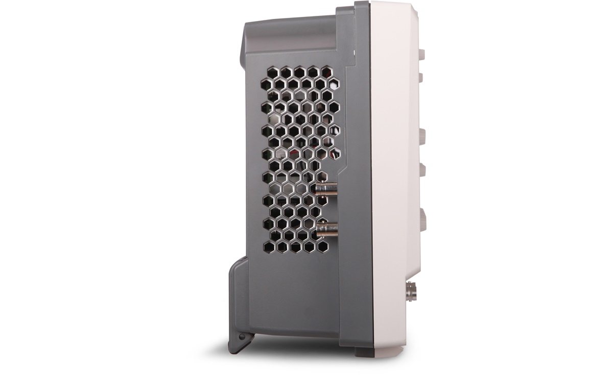
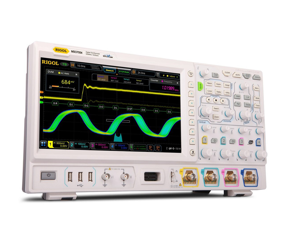
Rigol MSO7054
Precision You Can Trust
NABL-Accredited Calibration | Available on Request
Rs. 929073.00
The RIGOL MSO7054 is a 500 MHz, four-channel mixed-signal oscilloscope designed for embedded development, automotive electronics, industrial control, power testing and electronic product validation. It delivers up to 10 GSa/s real-time sampling, 100 Mpts standard memory expandable to 500 Mpts, 600,000 wfms/s capture, 16 digital-channel capability and an optional dual-channel 25 MHz waveform generator through a 10.1-inch touchscreen interface..
The RIGOL MSO7054 Mixed-Signal Oscilloscope is the 500 MHz model in the MSO7000 Series. It combines high-speed analogue acquisition, digital logic analysis, protocol decoding, waveform generation and advanced measurement tools in an expandable benchtop platform.
Built on RIGOL’s UltraVision II architecture and Phoenix chipset, the MSO7054 is designed to help engineers capture rare waveform events, analyse long signal records and correlate analogue behaviour with digital logic activity.
Core capabilities include:
- 500 MHz analogue bandwidth
- Four analogue input channels
- 16 digital-channel capability
- Up to 10 GSa/s real-time sampling
- 100 Mpts standard memory
- Optional memory depth up to 500 Mpts
- Up to 600,000 wfms/s waveform capture
- 8-bit vertical resolution
- Optional dual-channel 25 MHz waveform generator
- Optional embedded, automotive, audio and aerospace protocol analysis
- Full-memory automatic measurements
- 10.1-inch capacitive multi-touch display
The MSO7054 is suitable for embedded systems, industrial electronics, automotive modules, power converters, communication buses, IoT devices and general electronics research. RIGOL currently lists the MSO7054 with 500 MHz bandwidth, four analogue channels, 10 GSa/s maximum sampling, optional 500 Mpts memory and a 600,000 wfms/s capture rate.
500 MHz Analogue Bandwidth
The MSO7054 provides 500 MHz analogue bandwidth across four input channels.
This bandwidth supports measurements involving:
- Microcontrollers and embedded processors
- FPGA and CPLD systems
- Digital clock signals
- Automotive control modules
- Communication interfaces
- Switching power supplies
- Industrial control electronics
- Fast analogue circuits
- Sensor and actuator systems
- General signal-integrity troubleshooting
The conventional calculated rise time for a 500 MHz oscilloscope is approximately 700 ps. Actual system rise time also depends on the probe, input connection and measurement setup.
Four Analogue Channels
Four analogue channels allow engineers to capture and compare several related signals on a shared time base.
Typical measurements include:
- Clock, data, enable and reset
- Input and output signals
- Multiple supply rails
- Gate-drive and switching-node waveforms
- Sensor and actuator signals
- Communication transmit and receive lines
- Feedback and control-loop signals
- Multi-phase converter waveforms
A separate external trigger input allows another signal to trigger the acquisition without occupying an analogue measurement channel.
8-Bit Acquisition System
The MSO7054 uses an 8-bit analogue-to-digital converter, providing 256 vertical quantisation levels.
The oscilloscope’s acquisition and analysis tools help engineers examine:
- Signal amplitude
- Overshoot and undershoot
- Timing relationships
- Pulse behaviour
- Switching transitions
- Communication activity
- Noise and waveform instability
For measurements involving very small ripple or low-level noise, probe selection, bandwidth limiting, grounding and vertical-range configuration are especially important.
16-Channel Logic Analyser Capability
The MSO7054 supports 16 digital channels for mixed-signal measurements.
A compatible RPL2316 logic analyser probe is required to connect digital signals. The logic probe should therefore be listed as a required accessory rather than assumed to be included with every instrument.
Mixed-signal analysis allows analogue and digital activity to be viewed on the same time base.
Applications include:
- Microcontroller debugging
- FPGA and CPLD validation
- Parallel bus testing
- State-machine troubleshooting
- ADC and DAC validation
- Embedded firmware development
- Digital power control
- Analogue-to-digital event correlation
The MSO7054 provides the MSO platform functionality, while the physical digital inputs are accessed through the logic probe.
Up to 10 GSa/s Real-Time Sampling
The maximum sample rate depends on the active analogue-channel configuration.
| Active Analogue Channels | Maximum Sample Rate |
|---|---|
| One channel | 10 GSa/s |
| Two channels | 5 GSa/s per channel |
| Four channels | 2.5 GSa/s per channel |
The product should therefore be described as providing up to 10 GSa/s, rather than 10 GSa/s simultaneously on every channel.
At 500 MHz bandwidth and 10 GSa/s maximum sampling, the highest sample-rate-to-bandwidth ratio is 20:1 in the supported single-channel configuration.
High-speed sampling improves waveform reconstruction when analysing:
- Fast edges
- Narrow pulses
- Digital clocks
- Switching transitions
- Overshoot and ringing
- Serial communication
- Timing violations
- Intermittent glitches
Standard and Optional Memory Depth
The MSO7054 provides 100 Mpts standard single-channel acquisition memory.
Standard Memory Allocation
| Active Analogue Channels | Standard Memory |
|---|---|
| One channel | 100 Mpts |
| Two channels | 50 Mpts per channel |
| Four channels | 25 Mpts per channel |
Maximum Memory with Upgrade
| Active Analogue Channels | Maximum Memory |
|---|---|
| One channel | 500 Mpts |
| Two channels | 250 Mpts per channel |
| Four channels | 125 Mpts per channel |
The memory specification should therefore be written as 100 Mpts standard and up to 500 Mpts optional.
Deep memory is useful for:
- Long serial bus acquisitions
- Power-up and shutdown sequences
- Embedded-software debugging
- Communication packet analysis
- Intermittent fault investigation
- Multi-cycle timing measurements
- Detailed waveform zooming
- Long-duration signal monitoring
Up to 600,000 wfms/s Capture Rate
The MSO7054 provides waveform capture up to 600,000 waveforms per second.
A fast capture rate reduces acquisition dead time and increases the probability of finding uncommon events such as:
- Rare glitches
- Runt pulses
- Signal dropouts
- Timing violations
- Intermittent noise
- Unstable clocks
- Abnormal transitions
- Infrequent protocol errors
RIGOL identifies 600,000 wfms/s as a principal MSO7000 Series capability.
256-Level Intensity Grading
The digital phosphor display uses 256-level waveform-intensity grading.
Frequently occurring waveform activity appears more strongly, while uncommon events remain visible with lower intensity.
This helps engineers recognise:
- Multiple waveform states
- Rare glitches
- Noise bursts
- Modulated signals
- Timing variation
- Unstable transitions
Adjustable persistence can retain previous acquisitions on the display for easier comparison.
Full-Memory Automatic Measurements
The MSO7054 supports hardware-accelerated measurements across the complete acquisition record.
Measurements are not restricted to only the waveform segment currently shown on the screen.
The instrument supports 41 automatic waveform parameters, including:
- Frequency
- Period
- Peak-to-peak voltage
- Maximum and minimum voltage
- Average voltage
- RMS voltage
- Rise and fall time
- Positive and negative pulse width
- Duty cycle
- Overshoot
- Preshoot
- Phase
- Channel delay
Up to ten measurement results can be displayed with statistical analysis.
Full-memory measurement is useful for:
- Long clock records
- Deep serial bus acquisitions
- Multi-cycle signals
- Extended startup sequences
- Long-duration timing analysis
- Complete communication packets
Histogram Analysis
The MSO7054 supports horizontal, vertical and measurement histograms.
Horizontal Histogram
Used to evaluate:
- Clock jitter
- Edge-position variation
- Timing distribution
- Pulse-location stability
Vertical Histogram
Used to evaluate:
- Signal noise
- Amplitude distribution
- Reference-voltage variation
- Rail stability
Measurement Histogram
Used to evaluate:
- Long-term measurement distribution
- Production variation
- Repetitive test behaviour
- Signal stability over time
Mask and Pass/Fail Testing
Hardware pass/fail testing compares acquired waveforms against a user-defined mask.
This function is suitable for:
- Production-line testing
- Quality assurance
- Long-duration monitoring
- Component comparison
- Repetitive design validation
- Basic pre-compliance checks
The oscilloscope can count passing and failing acquisitions and provide an output based on the test result.
Enhanced FFT Analysis
The MSO7054 supports FFT processing with record lengths up to 1 Mpts under supported settings.
FFT analysis is useful for:
- Harmonic measurement
- Switching-frequency analysis
- Oscillation detection
- Noise-source identification
- Clock-spur analysis
- Filter evaluation
- EMI troubleshooting
- Power-electronics debugging
Users can configure frequency-domain views using:
- Centre frequency and span
- Start and stop frequency
- FFT window selection
- Peak searching
Supported FFT windows include rectangular, Hanning, Hamming, Blackman, flat-top and triangular windows.
Advanced Trigger Functions
The MSO7054 provides trigger modes for isolating specific signal conditions.
Trigger functions include:
- Edge
- Pulse width
- Slope
- Video
- Pattern
- Duration
- Timeout
- Runt
- Window
- Delay
- Setup and hold
- Nth edge
- Serial bus trigger
These triggers allow engineers to capture a specific abnormal event instead of manually searching through normal waveforms.
Serial Protocol Triggering and Decoding
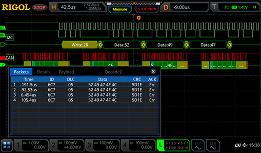
Optional protocol-analysis packages extend the MSO7054 for embedded, automotive, audio and aerospace systems.
Supported protocols can include:
Embedded Interfaces
- RS232/UART
- I²C
- SPI
Automotive Interfaces
- CAN
- LIN
- FlexRay
Audio Interface
- I²S
Aerospace Interface
- MIL-STD-1553
Up to four buses can be decoded simultaneously, depending on installed licences and available sources.
Protocol analysis helps identify:
- Incorrect addresses
- Invalid data
- Missing acknowledgements
- Frame errors
- Timing violations
- Communication interruptions
- Electrical waveform distortion
- Intermittent bus failures
Protocol licences should be listed as optional unless confirmed in the supplied bundle.
Search and Navigation
Waveform search and navigation help users locate selected events within long memory records.
Search conditions can include:
- Edge transitions
- Pulse-width conditions
- Runt pulses
- Logic patterns
- Setup and hold events
- Serial bus conditions
Matching events can be marked and reviewed individually, reducing the time required to analyse deep-memory acquisitions.
Optional Dual-Channel 25 MHz Waveform Generator
The optional MSO7000-AWG function adds two waveform-generator outputs.
Generator capabilities include:
- Two output channels
- 200 MSa/s sampling
- 14-bit vertical resolution
- Maximum sine-wave frequency of 25 MHz
- Square and pulse output up to 15 MHz
- Ramp output up to 100 kHz
- Noise bandwidth up to 25 MHz
- Arbitrary waveform output up to 10 MHz
Supported waveforms include:
- Sine
- Square
- Pulse
- Ramp
- Noise
- DC
- Built-in waveforms
- User-defined arbitrary waveforms
The generator is useful for:
- Circuit stimulation
- Amplifier testing
- Filter evaluation
- Sensor simulation
- Clock generation
- Embedded-system debugging
- Response measurements
The waveform-generator function is optional and should not be described as standard unless its licence is included. Current product listings identify MSO7000-AWG as the dual-channel 25 MHz generator upgrade.
Digital Voltmeter, Counter and Totaliser
The MSO7054 also provides integrated measurement functions such as:
- Digital voltmeter
- High-resolution frequency counter
- Totaliser or accumulator
These functions support routine voltage, frequency, period and event-count measurements without requiring separate instruments for basic checks.
10.1-Inch Capacitive Touchscreen
The oscilloscope includes a 10.1-inch capacitive multi-touch display with 1024 × 600 resolution.
The interface supports:
- Waveform dragging
- Horizontal and vertical zoom
- Cursor positioning
- Measurement selection
- Protocol decode display
- Digital-channel viewing
- Multi-window operation
- Gesture-based navigation
Physical knobs and front-panel buttons remain available for conventional oscilloscope control.
Connectivity and Remote Operation
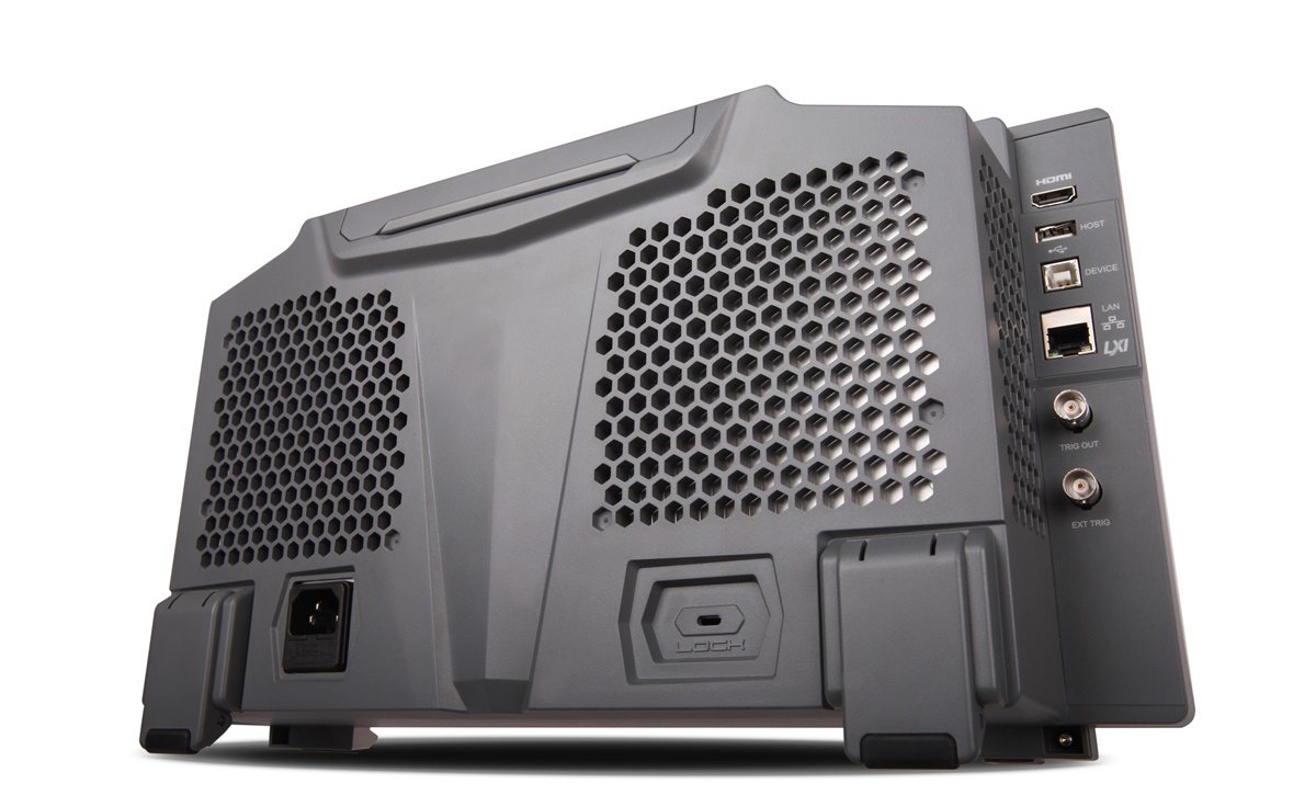
Available interfaces include:
- USB Host
- USB Device
- LAN
- LXI support
- HDMI
- Trigger and calibration output
- Optional USB-to-GPIB adapter
- SCPI remote programming
- Web-based remote access where supported
These interfaces support:
- USB storage
- PC communication
- Network control
- Automated test integration
- External monitor connection
- Screenshot transfer
- Waveform export
- Laboratory-system integration
Physical Design
The MSO7054 is designed for benchtop and system-testing environments.
Approximate physical specifications include:
- Width: 410 mm
- Height: 224 mm
- Depth: 135 mm
- Weight: approximately 3.9 kg
Its large screen and relatively shallow enclosure provide a clear interface without requiring excessive bench depth.
Applications
The RIGOL MSO7054 is suitable for:
- Embedded-system development
- Microcontroller debugging
- FPGA and CPLD validation
- Mixed-signal analysis
- Automotive electronics
- CAN, LIN and FlexRay testing
- Industrial control systems
- IoT hardware development
- Switching power supplies
- Power electronics
- Sensor and actuator testing
- Communication-interface debugging
- Production validation
- Quality-control testing
- Research and development
- Educational laboratories
- Automated test systems
- Service and repair
Why Buy from Revine Tech
Revine Tech supplies RIGOL oscilloscopes, logic analyser probes, waveform-generator options, protocol software and electronic measurement accessories.
Technical selection support can include:
- MSO7054 configuration
- 500 MHz bandwidth assessment
- Analogue and digital channel planning
- RPL2316 logic-probe selection
- Memory-depth upgrade
- Embedded and automotive protocol options
- Waveform-generator activation
- Power-analysis software
- Passive and active probe selection
- High-voltage differential probes
- Current probes
- Automated test integration
- Calibration and documentation
The final RIGOL MSO7054 price depends on the memory upgrade, logic probe, protocol licences, waveform-generator option, power-analysis software, probes, calibration and regional package.