
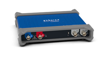
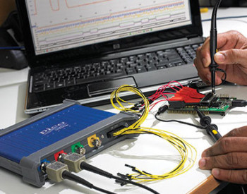
PicoScope® 3000D Series
Precision You Can Trust
NABL-Accredited Calibration | Available on Request
Rs. 11.00
The PicoScope 3000D Series USB Mixed-Signal Oscilloscope combines two or four analogue channels, 16 digital inputs, deep acquisition memory and an integrated function/arbitrary waveform generator in a compact PC-based instrument. Depending on the selected MSO model, it provides 50 MHz to 200 MHz bandwidth, up to 1 GS/s real-time sampling, 64 MS to 512 MS memory and up to 100,000 wfms/s for embedded development, serial decoding and electronics testing..
- Detail
- Special Features
- Specification
The PicoScope 3000D Series USB Mixed-Signal Oscilloscope is designed for engineers, technicians, research laboratories, electronics manufacturers and educational institutions that require analogue and digital signal analysis in a portable USB-connected instrument.
The MSO models combine:
- Two or four analogue oscilloscope channels
- Sixteen digital logic inputs
- 50 MHz to 200 MHz model-dependent bandwidth
- Up to 1 GS/s real-time sampling
- Up to 512 MS capture memory
- Up to 100,000 waveform captures per second
- Built-in function generator
- Built-in 12-bit arbitrary waveform generator
- Advanced digital triggering
- Serial protocol decoding
- FFT spectrum analysis
- PicoScope 7 software
- PicoSDK support
PicoScope 3000D instruments connect to a Windows, macOS or Linux computer and use its display, storage and processing resources. Their compact enclosure and USB-powered design make them suitable for laboratory, production, education and portable field-testing applications.
PicoScope 3000D MSO Model Range
The range includes both two-channel and four-channel mixed-signal configurations.
| Model | Analogue Channels | Digital Channels | Analogue Bandwidth | Buffer Memory |
|---|---|---|---|---|
| PicoScope 3203D MSO | 2 | 16 | 50 MHz | 64 MS |
| PicoScope 3204D MSO | 2 | 16 | 70 MHz | 128 MS |
| PicoScope 3205D MSO | 2 | 16 | 100 MHz | 256 MS |
| PicoScope 3206D MSO | 2 | 16 | 200 MHz | 512 MS |
| PicoScope 3403D MSO | 4 | 16 | 50 MHz | 64 MS |
| PicoScope 3404D MSO | 4 | 16 | 70 MHz | 128 MS |
| PicoScope 3405D MSO | 4 | 16 | 100 MHz | 256 MS |
| PicoScope 3406D MSO | 4 | 16 | 200 MHz | 512 MS |
The product page should use model-dependent wording because bandwidth and memory vary significantly across the range.
Two or Four Analogue Channels
The PicoScope 3000D Series is available with:
- Two analogue channels on 3200D MSO models
- Four analogue channels on 3400D MSO models
The analogue inputs are suitable for observing:
- Clock, data and enable signals
- Input and output waveforms
- Voltage and current
- Multiple power rails
- Sensor outputs
- PWM signals
- Switching power-supply waveforms
- Analogue amplifier signals
- Communication physical layers
- Phase and timing relationships
Four-channel models are useful when several related signals must be viewed simultaneously, while two-channel models provide a smaller and more cost-effective platform for paired signal measurements.
Sixteen Digital Logic Channels
Every PicoScope 3000D MSO model includes 16 digital inputs, arranged as two ports of eight channels.
The digital system provides:
- Channels D0 to D15
- Two independent threshold groups
- Maximum input frequency of 100 MHz
- Signal data rates up to approximately 200 Mb/s
- Minimum detectable pulse width of 5 ns
- ±20 V input range
- ±5 V threshold adjustment
- Time-correlated analogue and digital acquisition
- Logic pattern and edge triggering
The digital inputs can be displayed individually or grouped into buses with binary, decimal or hexadecimal values. This supports microcontroller, FPGA, CPLD and parallel bus debugging.
50 MHz to 200 MHz Analogue Bandwidth
The series offers four bandwidth options:
- 50 MHz
- 70 MHz
- 100 MHz
- 200 MHz
Calculated rise time ranges from:
- 7 ns on 50 MHz models
- 5 ns on 70 MHz models
- 3.5 ns on 100 MHz models
- 1.75 ns on 200 MHz models
A switchable 20 MHz hardware bandwidth limiter helps reduce high-frequency noise when the full model bandwidth is not required.
Typical applications include:
- Embedded-system debugging
- Microcontroller development
- FPGA testing
- Power-supply analysis
- PWM measurement
- Serial communication testing
- Sensor and actuator analysis
- Audio and general electronics
- Research and engineering education
Up to 1 GS/s Real-Time Sampling
The maximum real-time sampling rate depends on the number of enabled analogue channels and digital ports.
Typical allocation is:
- 1 GS/s with one analogue channel
- 500 MS/s with up to two analogue channels or digital ports
- 250 MS/s with up to four analogue channels or digital ports
- 125 MS/s with larger mixed analogue and digital configurations
One digital port represents eight digital channels. The available sampling rate is therefore affected when one or both digital ports are enabled.
High-speed sampling helps capture:
- Narrow pulses
- Fast waveform edges
- Overshoot and ringing
- Timing variation
- Communication errors
- Switching transients
- Intermittent glitches
- Signal dropouts
Equivalent-Time Sampling
For repetitive signals, supported models provide equivalent-time sampling rates up to 10 GS/s.
ETS performance depends on the model:
- Up to 2.5 GS/s on selected 50 MHz models
- Up to 5 GS/s on selected 70 MHz models
- Up to 10 GS/s on 100 MHz and 200 MHz configurations
Equivalent-time sampling is suitable for stable repetitive signals. It should not be used as the headline sample rate for single-shot or non-repetitive events.
Deep Buffer Memory
Buffer memory varies by model:
- 64 MS
- 128 MS
- 256 MS
- 512 MS
Deep memory allows engineers to:
- Capture long-duration waveforms
- Maintain higher sampling rates on slower time bases
- Zoom into individual events
- Record serial communication packets
- Analyse start-up sequences
- Investigate intermittent faults
- Compare repeated acquisitions
- Examine timing variation over long records
The highest-memory 3206D MSO and 3406D MSO models provide up to 512 million samples.
Segmented Memory and Rapid Triggering
The PicoScope 3000D Series supports segmented acquisition, allowing buffer memory to be divided into individual waveform records.
PicoScope software supports up to:
- 40,000 waveform segments
PicoSDK supports model-dependent segment counts of up to:
- 130,000
- 250,000
- 500,000
- 1,000,000
Rapid triggering can capture closely spaced events with a typical trigger rearm time below 0.7 µs under specified conditions.
Segmented acquisition is useful for:
- Serial packets
- Injector or ignition pulses
- Switching events
- Rare glitches
- Production test cycles
- Repetitive control signals
- Intermittent faults
Up to 100,000 Waveforms per Second
The hardware acceleration engine supports waveform capture and display rates up to approximately 100,000 wfms/s, depending on the connected computer and acquisition settings.
Fast waveform updates improve the probability of detecting:
- Rare glitches
- Runt pulses
- Timing violations
- Unstable waveform edges
- Intermittent noise
- Communication faults
- Signal dropouts
- Abnormal pulse widths
Hardware acceleration processes waveform data inside the oscilloscope before transferring display information to the computer, reducing the burden on the USB connection and host processor.
Built-In Function Generator
Every PicoScope 3000D model includes a function generator.
Supported waveforms include:
- Sine
- Square
- Triangle
- DC
- Ramp
- Sinc
- Gaussian
- Half-sine
- White noise
- PRBS
The generator supports:
- Frequencies from DC to 1 MHz
- Upward, downward and dual sweeps
- Triggered or free-running operation
- Adjustable amplitude and DC offset
- ±2 V overall output range
The generator output is located on the rear panel of MSO models.
Built-In 12-Bit Arbitrary Waveform Generator
The integrated AWG provides:
- 12-bit output resolution
- 20 MS/s update rate
- 32 kS waveform memory
- Greater than 1 MHz analogue bandwidth
- Custom waveform creation
- Captured waveform replay
- Imported waveform support
The AWG can be used for:
- Amplifier testing
- Filter evaluation
- Sensor simulation
- Circuit stimulus generation
- Relay testing
- Clock generation
- Education and laboratory experiments
- Production validation
Serial Protocol Decoding
PicoScope 7 includes serial protocol decoding as standard, without separate paid decoding licences.
Supported protocols include common embedded, automotive, industrial, audio and aerospace buses such as:
- I²C
- SPI
- UART and RS232
- CAN and CAN FD
- CAN XL
- LIN
- FlexRay
- I²S
- USB
- Ethernet
- BroadR-Reach
- 10BASE-T1S
- ARINC 429
- MIL-STD-1553
- Modbus
- SENT
- PSI5
- PMBus
- SMBus
- Parallel bus
Decoded data can be shown beside the waveform, in a table or in both formats. All analogue and digital channels may be used as protocol sources, subject to the available bandwidth and channel count.
Advanced Digital Triggering
The PicoScope 3000D Series provides advanced triggering using digitised waveform data.
Trigger types include:
- Edge
- Window
- Pulse width
- Window pulse width
- Dropout
- Window dropout
- Interval
- Logic
- Runt pulse
- Digital pattern
- Combined pattern and edge
MSO models can trigger on any selected combination of analogue and digital conditions. This is useful for isolating timing errors, setup and hold violations, incomplete pulses and communication faults.
FFT Spectrum Analysis
PicoScope software includes an FFT spectrum analyser with:
- Frequency range from DC to the oscilloscope bandwidth
- Up to one million FFT points
- Magnitude, peak-hold and average modes
- Linear and logarithmic frequency axes
- Multiple window functions
- Harmonic and distortion measurements
Spectrum measurements include:
- Frequency at peak
- Amplitude at peak
- Total power
- THD
- THD+N
- SFDR
- SINAD
- SNR
- Intermodulation distortion
This is useful for harmonic analysis, switching noise investigation, filter testing and identifying unwanted oscillations.
Waveform Mathematics and Power Analysis
PicoScope software supports waveform mathematics such as:
- Addition
- Subtraction
- Multiplication
- Division
- Integration
- Differentiation
- RMS
- Frequency
- Duty cycle
- Phase and delay
- Low-pass filtering
- High-pass filtering
- Band-pass filtering
- Band-stop filtering
Power-related calculations include:
- True power
- Apparent power
- Reactive power
- Power factor
- DC power
- Crest factor
- Energy-related area measurements
Custom maths channels can be displayed alongside acquired and reference waveforms.
Mask Limit Testing
Mask testing compares live waveforms against a defined reference envelope.
Masks can be:
- Automatically generated
- User-drawn
- Entered as a table
- Imported from a file
Available actions include:
- Highlighting failed waveforms
- Selecting failures in the waveform buffer
- Activating an alarm
- Saving captures
- Stopping or restarting acquisition
- Running an external program
This supports production testing, repetitive quality checks and long-duration fault monitoring.
PicoScope 7 Software
PicoScope 7 is available for:
- Windows
- macOS
- Linux
The software provides:
- Oscilloscope views
- Spectrum analysis
- Serial decoding
- Automatic measurements
- Waveform mathematics
- Mask testing
- Reference waveforms
- Custom probes
- Automated actions
- Segmented memory
- Waveform buffer navigation
- Measurement statistics
PicoScope 7 and protocol decoding are included without recurring software licence charges.
PicoSDK and Automated Test Integration
PicoSDK provides direct control of the PicoScope 3000D hardware for custom software and automated systems.
It can support:
- C
- C++
- C#
- Visual Basic .NET
- MATLAB
- LabVIEW
- Microsoft Excel integration
- Bespoke production software
Continuous streaming can reach up to approximately 125 MS/s through PicoSDK, depending on computer performance and application configuration.
Compact USB-Powered Design
The PicoScope 3000D Series enclosure measures approximately:
- 190 mm wide
- 170 mm deep
- 40 mm high
Weight is below 0.5 kg.
The instruments are powered through:
- One USB 3.0 port
- Two USB 2.0 ports
- Included AC adaptor for four-channel models when required
This compact design is suitable for:
- Laptop-based field testing
- Portable engineering kits
- Small workbenches
- Educational laboratories
- Automated test fixtures
- OEM integration
- Service and repair applications
Applications
The PicoScope 3000D Series MSO is suitable for:
- Embedded-system development
- Microcontroller debugging
- FPGA and CPLD testing
- Mixed-signal circuit analysis
- Digital logic analysis
- Serial protocol debugging
- Power electronics
- Switching power-supply analysis
- Automotive electronics
- Sensor and actuator testing
- Analogue circuit development
- Research and development
- Production-line testing
- Electronic service and repair
- Engineering education
- Portable field measurement
- OEM and automated test integration
Two or Four Analogue Channels
Available configurations include:
- Two analogue channels with 16 digital inputs
- Four analogue channels with 16 digital inputs
Sixteen Digital Channels
MSO models provide:
- Two groups of eight digital inputs
- 100 MHz maximum digital input frequency
- 5 ns minimum pulse width
- Logic bus grouping
- Analogue and digital correlation
50 MHz to 200 MHz Bandwidth
Available bandwidths include:
- 50 MHz
- 70 MHz
- 100 MHz
- 200 MHz
Up to 1 GS/s Real-Time Sampling
Sampling performance varies with the number of active analogue channels and digital ports.
Up to 512 MS Memory
Available memory depths include:
- 64 MS
- 128 MS
- 256 MS
- 512 MS
Up to 100,000 wfms/s
Fast acquisition helps locate rare glitches, timing errors and intermittent faults.
Built-In Function Generator and AWG
Every model includes:
- 1 MHz function generator
- 12-bit AWG
- 20 MS/s AWG update rate
- 32 kS arbitrary waveform memory
Serial Decoding Included
PicoScope 7 provides more than 40 protocol decoders without separate paid licences.
USB 3.0 Connectivity
The compact instrument is powered and controlled through USB, with an AC adaptor included for four-channel models where required.
Core Series Specifications
| Specification | PicoScope 3000D Series MSO |
|---|---|
| Product type | USB mixed-signal oscilloscope |
| Analogue channels | 2 or 4 |
| Digital channels | 16 |
| Analogue bandwidth | 50 MHz to 200 MHz |
| Maximum real-time sample rate | 1 GS/s |
| Maximum ETS rate | Up to 10 GS/s |
| Buffer memory | 64 MS to 512 MS |
| Maximum waveform capture | Up to 100,000 wfms/s |
| Vertical resolution | 8 bits |
| Enhanced resolution | Software-supported |
| Function generator | Included |
| AWG | Included, 12-bit |
| Serial decoding | Included in PicoScope 7 |
| Spectrum analyser | Included |
| PC interface | USB 3.0 |
| Software | PicoScope 7 |
| SDK | PicoSDK |
| Warranty | Five years |
Model Comparison
| Model | Analogue Channels | Bandwidth | Maximum Memory |
|---|---|---|---|
| 3203D MSO | 2 | 50 MHz | 64 MS |
| 3204D MSO | 2 | 70 MHz | 128 MS |
| 3205D MSO | 2 | 100 MHz | 256 MS |
| 3206D MSO | 2 | 200 MHz | 512 MS |
| 3403D MSO | 4 | 50 MHz | 64 MS |
| 3404D MSO | 4 | 70 MHz | 128 MS |
| 3405D MSO | 4 | 100 MHz | 256 MS |
| 3406D MSO | 4 | 200 MHz | 512 MS |
Sampling Allocation
| Active Acquisition Resources | Maximum Real-Time Sampling |
|---|---|
| One analogue channel | 1 GS/s |
| Up to two analogue channels or digital ports | 500 MS/s |
| Up to four analogue channels or digital ports | 250 MS/s |
| Other analogue and digital combinations | 125 MS/s |
A digital port consists of eight digital channels.
Analogue Input System
| Specification | Details |
|---|---|
| Input ranges | ±20 mV to ±20 V full scale |
| Input sensitivity | 4 mV/div to 4 V/div |
| Input coupling | AC or DC |
| Input impedance | 1 MΩ in parallel with approximately 14 pF |
| Vertical resolution | 8 bits |
| Hardware bandwidth limiter | 20 MHz |
| DC accuracy | ±3% full scale ±200 µV |
| Overvoltage protection | ±100 V DC plus AC peak |
| Sampling | Simultaneous on enabled channels |
Digital Input System
| Specification | Details |
|---|---|
| Digital channels | 16 |
| Port grouping | D0–D7 and D8–D15 |
| Maximum input frequency | 100 MHz |
| Maximum data rate | Approximately 200 Mb/s |
| Minimum pulse width | 5 ns |
| Input impedance | 200 kΩ in parallel with approximately 8 pF |
| Input range | ±20 V |
| Threshold range | ±5 V |
| Overvoltage protection | ±50 V |
| Threshold controls | Two independently adjustable groups |
Function Generator and AWG
| Specification | Details |
|---|---|
| Function generator frequency | DC to 1 MHz |
| Standard waveforms | Sine, square, triangle, ramp, sinc, Gaussian, half-sine, noise and PRBS |
| Sweep modes | Up, down and dual |
| Output range | ±2 V |
| AWG resolution | 12 bits |
| AWG update rate | 20 MS/s |
| AWG memory | 32 kS |
| AWG bandwidth | Greater than 1 MHz |
| Output impedance | 600 Ω |
Software and Analysis
| Function | Capability |
|---|---|
| PicoScope software | PicoScope 7 |
| Supported operating systems | Windows, macOS and Linux |
| Serial protocol decoding | More than 40 protocols |
| FFT points | Up to 1 million |
| Mask testing | Supported |
| Automatic measurements | Voltage, timing, power and spectrum |
| Waveform maths | Advanced functions and digital filters |
| Measurement statistics | Minimum, maximum, average and standard deviation |
| Automated actions | Supported |
| Custom probes | Supported |
| Segmented memory | Up to 40,000 buffers in PicoScope software |
Connectivity and Physical Specifications
| Specification | Details |
|---|---|
| PC connection | USB 3.0 SuperSpeed |
| USB 2.0 support | Supported |
| Dimensions | Approximately 190 × 170 × 40 mm |
| Weight | Less than 0.5 kg |
| Power | USB powered |
| Four-channel power support | AC adaptor included when required |
| Operating temperature | 0°C to 40°C |
| Maximum altitude | 2,000 m |
| Warranty | Five years |