
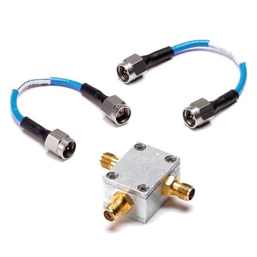
14 GHz power divider kit
Precision You Can Trust
NABL-Accredited Calibration | Available on Request
The TA238 14 GHz Power Divider Kit is designed for use with PicoScope 9300 Series sampling oscilloscopes in high-speed clock-recovery and TDR/TDT applications. The kit includes an 18 GHz, 50 Ω, SMA female-female-female 3-resistor 6 dB power divider and two 10 cm precision SMA male-to-male coaxial cables. It is used to split high-speed signals into separate paths for data, clock and time-domain measurement setups..
- Detail
- Special Features
- Specification
The TA238 14 GHz Power Divider Kit is a passive RF accessory intended for high-bandwidth sampling oscilloscope measurements with the PicoScope 9300 Series.
Pico specifies the kit for two main applications: splitting a data signal between the data input and clock-recovery trigger input on supported sampling oscilloscopes, and configuring TDR/TDT measurement systems. One TA238 kit is required per channel in these applications.
The kit contains:
- 18 GHz, 50 Ω, 3-resistor power divider
- 6 dB nominal divider configuration
- Three SMA female RF ports
- Two 10 cm precision coaxial cables
- SMA male-to-male cable connections
- Passive operation with no external power or software control
18 GHz 3-Resistor Power Divider
The core component in the TA238 kit is an 18 GHz 50 Ω SMA female-female-female 3-resistor 6 dB power divider.
Its purpose is to divide one incoming high-speed signal into two output paths. This allows the same signal to be routed simultaneously to different parts of a measurement system.
Typical uses include:
- Data and clock signal splitting
- Clock-recovery triggering
- TDR measurement paths
- TDT measurement paths
- High-speed sampling oscilloscope setups
- Signal-integrity laboratory measurements
Because all three RF interfaces are SMA female, the supplied SMA male-to-male cables provide the required interconnection to compatible equipment.
Two Precision 10 cm SMA Cables
The TA238 includes two 10 cm precision coaxial cables with SMA male connectors at both ends.
Short precision cables help minimise additional:
- Signal loss
- Electrical delay
- Phase variation
- Reflections
- High-frequency degradation
This is especially important in sampling-oscilloscope applications where picosecond timing and high-frequency waveform fidelity matter.
Clock-Recovery Applications
Pico specifically requires the TA238 when a high-speed data signal must be split between:
- The main data input
- The clock-recovery trigger input
This configuration is used with:
- PicoScope 9302
- PicoScope 9321
One TA238 kit is required per channel when the data signal is split for clock-recovery operation.
A typical signal path is:
Incoming data signal → TA238 power divider → data input + clock-recovery trigger input
This allows the sampling oscilloscope to observe the waveform while simultaneously deriving the timing reference required for stable acquisition.
Why Clock Recovery Needs Signal Splitting
In many high-speed serial systems, a separate external clock is not available.
The receiver or measurement instrument must recover timing information from the data stream itself.
The TA238 allows the same physical signal to feed:
- The waveform acquisition path
- The clock-recovery path
This arrangement helps support stable eye-diagram and timing measurements on serial data signals.
TDR and TDT Applications
Pico also specifies the TA238 for TDR/TDT applications with PicoScope 9300 Series sampling oscilloscopes. One kit is required per channel.
For TDR/TDT work, the TA238 is used together with the separate TA237 14 GHz TDR accessory kit.
A typical configuration may include:
- PicoScope 9300 Series sampling oscilloscope
- TA238 power divider kit
- TA237 TDR accessory kit
- Appropriate fast pulse source
- Device or transmission path under test
The TA238 is therefore an important signal-routing component rather than the complete TDR system itself.
Relationship with TA237 TDR Kit
The TA237 and TA238 serve different functions.
The TA237 provides:
- Reference short
- Reference load
- Precision cable
- TDR connection and calibration accessories
The TA238 provides:
- 6 dB power division
- Signal splitting
- Two short precision cables
Pico states that TDR/TDT applications using the TA238 also require the TA237 TDR accessory kit.
PicoScope 9300 Series Compatibility
The TA238 is specifically designed for PicoScope 9300 Series sampling oscilloscopes.
Relevant applications include:
- PicoScope 9302 clock-recovery measurements
- PicoScope 9321 optical and clock-recovery measurements
- PicoScope 9300 TDR/TDT configurations
- High-speed serial-data testing
- Signal-integrity analysis
The kit should not be described as a general-purpose standalone RF splitter without mentioning its intended PicoScope 9300 measurement role.
Passive RF Accessory
The TA238 is entirely passive.
It does not require:
- USB power
- External DC power
- Software control
- PicoSDK
- Firmware
- Network connection
- Electronic switching
Its function is determined solely by its RF divider network and connected cables.
50 Ω Measurement Environment
The TA238 power divider uses a 50 Ω impedance system, matching the high-frequency input environment used by PicoScope 9300 Series sampling oscilloscopes.
Maintaining consistent impedance helps reduce:
- Reflections
- Standing waves
- Signal distortion
- Measurement uncertainty
Correct 50 Ω interconnections are especially important at multi-gigahertz frequencies.
6 dB Power Division
The divider is specified as a 6 dB 3-resistor power divider.
This means the signal level at each output path is intentionally reduced relative to the input.
The loss should be considered when:
- Setting input sensitivity
- Configuring clock-recovery thresholds
- Evaluating signal amplitude
- Comparing direct and divided signal paths
The TA238 should therefore not be described as a zero-loss signal splitter.
Applications
The TA238 is suitable for:
- High-speed serial data testing
- Clock-recovery measurements
- Eye-diagram analysis
- PicoScope 9302 measurements
- PicoScope 9321 measurements
- TDR testing
- TDT testing
- Signal-integrity development
- High-speed interconnect characterisation
- Sampling oscilloscope laboratories
- Telecom development
- Optical communication testing
- Research and engineering education
Why Buy from RevineTech?
RevineTech can supply the TA238 together with compatible PicoScope 9300 Series oscilloscopes, TDR accessories and RF interconnect components.
Technical selection support can include:
- TA238 power-divider kit selection
- PicoScope 9302 and 9321 compatibility
- TA237 TDR kit selection
- TDR/TDT system configuration
- Clock-recovery measurement setup
- SMA cable and adaptor selection
- Sampling oscilloscope accessory planning
18 GHz Power Divider
The kit includes an:
- 18 GHz rated power divider
- 50 Ω impedance
- Three SMA female ports
- 3-resistor topology
- 6 dB divider configuration
Two Precision Coaxial Cables
Includes:
- 2 × 10 cm precision coaxial cables
- SMA male-to-male connectors
Clock-Recovery Signal Splitting
Designed to split one high-speed data signal between:
- Data input
- Clock-recovery trigger input
Supported specifically for PicoScope 9302 and 9321 applications.
TDR/TDT Support
Required for PicoScope 9300 Series TDR/TDT applications, with one kit per channel. The separate TA237 TDR accessory kit is also required.
Passive Operation
- No external power
- No USB connection
- No software
- No firmware
Core Technical Specifications
| Specification | Details |
|---|---|
| Product Name | 14 GHz Power Divider Kit |
| Pico Order Code | TA238 |
| Product Type | High-frequency passive power-divider accessory kit |
| Divider Bandwidth Rating | 18 GHz component |
| Intended System Bandwidth | 14 GHz applications |
| Divider Impedance | 50 Ω |
| Divider Type | 3-resistor |
| Nominal Division | 6 dB |
| Divider Connectors | SMA female-female-female |
| Precision Cables | 2 |
| Cable Length | 10 cm each |
| Cable Connectors | SMA male-to-male |
| Primary Applications | Clock recovery and TDR/TDT |
| Compatible Product Family | PicoScope 9300 Series |
| External Power | Not required |
| Software Control | Not required |
These kit contents and applications are confirmed by Pico’s current TA238 product page.
Kit Contents
| Component | Quantity | Specification |
|---|---|---|
| Power divider | 1 | 18 GHz, 50 Ω, SMA female-female-female, 3-resistor, 6 dB |
| Precision coaxial cable | 2 | 10 cm, SMA male-to-male |
Clock-Recovery Configuration
| Component | Function |
|---|---|
| High-speed data source | Provides serial data signal |
| TA238 | Splits incoming signal |
| Data input | Receives one divided signal |
| Clock-recovery input | Receives second divided signal |
| PicoScope 9302 / 9321 | Performs waveform acquisition and clock-recovery triggering |
TDR/TDT Configuration
| Component | Function |
|---|---|
| PicoScope 9300 Series | Sampling waveform acquisition |
| TA238 | Signal splitting |
| TA237 | TDR connection and calibration accessories |
| Pulse source | Generates fast TDR stimulus where required |
| DUT | Cable, PCB, connector or transmission structure |