Home PICO | RF Products Attenuator 10 dB 10 GHz 50 Ω SMA (m-f)
PICO | RF Products

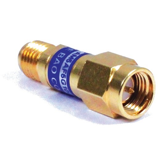
Attenuator 10 dB 10 GHz 50 Ω SMA (m-f)

Precision You Can Trust
NABL-Accreditied Calibration | Available on Request

The Pico TA262 is a precision 10 dB fixed RF attenuator designed for 50 Ω test and measurement systems. Operating from DC to 10 GHz with a 2 W power rating, it features SMA male-to-female connectivity for convenient inline integration. Its controlled VSWR and attenuation accuracy make it suitable for RF, microwave, VNA, signal-conditioning and laboratory measurement applications..

  • Detail
  • Special Features
  • Specification

The Pico TA262 10 dB 10 GHz 50 Ω SMA attenuator is a fixed RF attenuation accessory designed to reduce signal amplitude by a defined 10 dB while maintaining predictable performance across a wide frequency range.

It is intended for 50 Ω RF and microwave systems and operates from DC to 10 GHz, making it suitable for broadband measurement environments. The SMA male-to-female configuration allows the attenuator to be installed directly between compatible RF instruments, cables, adapters and devices under test.

The TA262 belongs to Pico Technology’s family of fixed 10 GHz attenuators, which also includes 3 dB, 6 dB and 20 dB versions. The TA262 provides the 10 dB attenuation option for applications requiring controlled reduction of RF signal level.

RF Measurement Performance

The TA262 maintains specified attenuation accuracy across its operating range:

  • DC to 2 GHz: ±0.2 dB attenuation deviation
  • 2 GHz to 5 GHz: ±0.3 dB attenuation deviation
  • 5 GHz to 10 GHz: ±0.5 dB attenuation deviation

Its frequency-dependent VSWR specification helps maintain predictable RF performance:

  • DC to 2 GHz: VSWR ≤ 1.1
  • 2 GHz to 5 GHz: VSWR ≤ 1.25
  • 5 GHz to 10 GHz: VSWR ≤ 1.35

These specifications make the TA262 suitable for engineers who require a defined attenuation level across broadband RF measurement setups.

Typical Applications

The Pico TA262 can be used in:

  • RF and microwave test benches
  • Vector network analyzer measurement setups
  • RF signal-level control
  • Signal generator test configurations
  • Receiver and device testing
  • Amplifier and RF component evaluation
  • Laboratory signal-conditioning setups
  • Research and development testing
  • RF prototype validation
  • Broadband measurement systems
  • Test fixture and cable interconnections

50 Ω RF System Compatibility

The TA262 is designed specifically for 50 Ω systems, the standard impedance used by many RF and microwave instruments, VNAs, signal generators, RF test cables and laboratory accessories.

Using the correct impedance throughout an RF measurement chain helps maintain consistent test conditions and reduces measurement uncertainty caused by impedance discontinuities.

Inline SMA Configuration

The SMA male-to-SMA female configuration allows the TA262 to be inserted directly into compatible RF signal paths without requiring a separate gender-changing adapter in many common test setups.

This makes it useful where a compact fixed attenuator is needed between:

  • RF cables
  • Test instruments
  • Measurement ports
  • Devices under test
  • RF adapters
  • Laboratory test fixtures


10 dB Fixed Attenuation

The TA262 provides a fixed nominal attenuation of 10 dB, allowing engineers to reduce RF signal amplitude by a known amount during measurement, validation and laboratory testing.

Wide DC to 10 GHz Frequency Range

Its broadband operating range from DC to 10 GHz supports a wide variety of RF and microwave measurements without requiring separate attenuators for lower and higher frequency ranges.

50 Ω System Impedance

The attenuator is designed for 50 Ω RF systems, making it suitable for integration with commonly used laboratory RF instruments, cables and test accessories.

2 W Power Rating

The TA262 has a rated power handling capability of 2 W, providing a defined operating limit for RF test and measurement applications.

The applied RF power should remain within the manufacturer’s specified rating.

Controlled VSWR Across the Frequency Range

The specified VSWR increases gradually with frequency:

  • ≤ 1.1 from DC to 2 GHz
  • ≤ 1.25 from 2 GHz to 5 GHz
  • ≤ 1.35 from 5 GHz to 10 GHz

This frequency-specific specification provides engineers with more useful information than a single typical VSWR value.

Defined Attenuation Accuracy

The TA262 provides specified attenuation deviation across three frequency bands:

  • ±0.2 dB from DC to 2 GHz
  • ±0.3 dB from 2 GHz to 5 GHz
  • ±0.5 dB from 5 GHz to 10 GHz

This allows users to account for expected attenuation variation when planning RF measurements.

SMA Male-to-Female Connectivity

The SMA male-to-female connector arrangement enables simple inline installation in compatible RF measurement chains and helps reduce the need for additional adapters.

Fixed Attenuator Design

Unlike a variable attenuator, the TA262 provides a predefined 10 dB attenuation level, making it suitable for repeatable test configurations where the same signal reduction is required consistently.

RoHS Compliant

The Pico Technology TA262 is RoHS compliant, meeting applicable restrictions on hazardous substances for electronic products and accessories.

Part of Pico Technology’s 10 GHz Attenuator Range

Pico Technology offers the same fixed-attenuator family in multiple attenuation values:

  • TA181: 3 dB
  • TA261: 6 dB
  • TA262: 10 dB
  • TA173: 20 dB
Specification Details
Manufacturer Pico Technology
Model / Part Number TA262
Product Type Fixed RF Attenuator
Nominal Attenuation 10 dB
Frequency Range DC to 10 GHz
System Impedance 50 Ω
Power Rating 2 W
Connector Type SMA Male to SMA Female
Attenuation Deviation, DC to 2 GHz ±0.2 dB
Attenuation Deviation, 2 to 5 GHz ±0.3 dB
Attenuation Deviation, 5 to 10 GHz ±0.5 dB
VSWR, DC to 2 GHz ≤ 1.1
VSWR, 2 to 5 GHz ≤ 1.25
VSWR, 5 to 10 GHz ≤ 1.35
Compliance RoHS compliant
Connection Configuration Inline SMA male-female
Primary Applications RF testing, microwave measurements, VNA setups, signal-level control and laboratory test systems
Live in Bengaluru electronica India 2026 · Sept 16 to 18 · BIEC Booth H3.J15, Hall 3 Loading... Book a meeting