
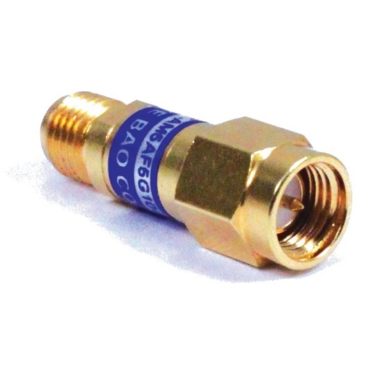
Attenuator 6 dB 10 GHz 50 Ω SMA (m-f)
Precision You Can Trust
NABL-Accredited Calibration | Available on Request
The Pico TA261 is a precision 6 dB fixed RF attenuator designed for 50 Ω RF and microwave systems from DC to 10 GHz. It offers 2 W power handling, SMA male-to-female connectivity, controlled attenuation accuracy and low VSWR for signal-level reduction, measurement-system protection, impedance matching support and RF test setups involving VNAs, signal generators, spectrum analyzers and oscilloscopes..
- Detail
- Special Features
- Specification
The Pico TA261 6 dB RF Attenuator is a compact passive RF accessory designed to reduce signal power by a nominal 6 dB while maintaining a controlled 50 Ω impedance environment.
A 6 dB attenuation corresponds to reducing signal power to approximately one quarter of the input power under ideal matched conditions. The voltage amplitude across equal impedances is reduced to approximately 50% of the original value.
The TA261 operates from DC to 10 GHz, making it suitable for laboratory, RF development, microwave testing, production validation and measurement-system integration.
DC to 10 GHz Frequency Range
The wide operating range allows the TA261 to be used across low-frequency, RF and microwave applications.
Typical compatible equipment includes:
- Vector network analyzers
- Spectrum analyzers
- RF signal generators
- RF receivers
- High-bandwidth oscilloscopes
- RF amplifiers
- Filters
- Antenna test setups
- Communication test systems
- RF development boards
- Production test fixtures
The same attenuator can remain in the signal path across a broad frequency span without changing accessories.
Fixed 6 dB Attenuation
The TA261 provides nominal 6 dB attenuation.
This level of attenuation is useful when a larger signal reduction is required than a 3 dB attenuator can provide.
Typical applications include:
- Reducing source signal level
- Protecting sensitive RF instrument inputs
- Controlling amplifier drive level
- Conditioning RF signals
- Improving measurement repeatability
- Reducing mismatch interaction between connected devices
- Preventing excessive signal levels from reaching receivers
Controlled Attenuation Accuracy
Pico specifies attenuation deviation according to frequency.
The TA261 provides:
- ±0.2 dB from DC to 2 GHz
- ±0.3 dB from 2 GHz to 5 GHz
- ±0.5 dB from 5 GHz to 10 GHz
This means the actual attenuation remains close to the nominal 6 dB value across the operating frequency range.
Approximate attenuation limits are:
- 5.8 to 6.2 dB from DC to 2 GHz
- 5.7 to 6.3 dB from 2 GHz to 5 GHz
- 5.5 to 6.5 dB from 5 GHz to 10 GHz
Low VSWR Performance
Low VSWR helps reduce unwanted RF reflections in a 50 Ω measurement system.
Pico specifies:
- VSWR ≤1.10 from DC to 2 GHz
- VSWR ≤1.25 from 2 GHz to 5 GHz
- VSWR ≤1.35 from 5 GHz to 10 GHz
These limits support predictable RF performance when the attenuator is connected within a properly terminated 50 Ω system.
50 Ω System Compatibility
The TA261 is designed for 50 Ω RF systems.
It can be integrated with compatible:
- RF cables
- VNAs
- Spectrum analyzers
- Oscilloscopes with 50 Ω inputs
- RF signal generators
- Receivers
- Amplifiers
- Filters
- Test fixtures
- Measurement accessories
Maintaining a consistent 50 Ω signal path helps reduce reflections and measurement errors.
2 W Power Handling
The TA261 is rated for 2 W maximum RF power.
This makes it suitable for low-to-moderate power RF test applications such as:
- Laboratory signal conditioning
- Receiver protection
- Source-level reduction
- VNA measurements
- Filter testing
- RF component characterization
The applied power must remain within the manufacturer’s specified limit.
SMA Male-to-Female Configuration
The TA261 uses an SMA male connector on one side and SMA female connector on the other.
This inline configuration allows direct connection between compatible RF equipment without requiring an additional adaptor.
Typical installation examples include:
RF source → TA261 → device under test
or
Device under test → TA261 → measurement instrument
Reducing the number of additional RF adaptors can help limit extra insertion loss, mismatch and connection uncertainty.
Passive Operation
The TA261 is a passive RF component.
It requires:
- No external power supply
- No software
- No control interface
- No active electronics
This makes it simple to integrate into fixed or temporary RF measurement setups.
RF Instrument Protection
The TA261 can be used ahead of sensitive measurement inputs to reduce incoming signal power.
Typical applications include:
- Spectrum analyzer protection
- VNA receiver protection
- Oscilloscope input protection
- RF receiver input conditioning
- Measurement module protection
The remaining signal level after attenuation must still remain within the safe input rating of the connected instrument.
Improved Measurement Matching
Fixed attenuators are commonly used between RF devices to reduce the influence of imperfect impedance matching.
The TA261 can improve test consistency in:
- Network analyzer measurements
- RF amplifier testing
- Filter characterization
- Return-loss measurements
- Signal-generator setups
- Receiver testing
- Production RF systems
The final result depends on the complete source, cable, attenuator and load configuration.
Cascaded Attenuation
Multiple fixed attenuators can be connected in series when greater attenuation is required.
For example:
- 3 dB + 6 dB ≈ 9 dB
- 6 dB + 10 dB ≈ 16 dB
- 6 dB + 20 dB ≈ 26 dB
Power handling and connector compatibility should always be checked before cascading attenuators.
Pico offers related fixed attenuators in the same family:
| Model | Nominal Attenuation |
|---|---|
| TA181 | 3 dB |
| TA261 | 6 dB |
| TA262 | 10 dB |
| TA173 | 20 dB |
All four models are specified for DC to 10 GHz, 50 Ω operation and 2 W power handling.
Applications
The Pico TA261 is suitable for:
- RF signal-level reduction
- Vector network analyzer testing
- Spectrum analyzer setups
- RF amplifier testing
- Filter characterization
- Receiver sensitivity testing
- Signal-generator conditioning
- RF laboratory measurements
- Production test systems
- Microwave development
- Antenna test setups
- RF education and training
- General 50 Ω signal conditioning
Why Buy from RevineTech?
RevineTech supplies Pico Technology RF accessories and measurement products for research, RF laboratories, electronics development, education and production testing.
Technical selection support can help users choose the correct fixed attenuator, RF cable, adaptor or VNA accessory based on attenuation requirement, operating frequency, connector type, power level and measurement setup.
The Pico TA261 provides broadband fixed attenuation in a compact SMA inline format.
Key features include:
- Nominal 6 dB attenuation
- DC to 10 GHz operating range
- 50 Ω characteristic impedance
- 2 W power rating
- SMA male-to-female configuration
- VSWR ≤1.10 from DC to 2 GHz
- VSWR ≤1.25 from 2 GHz to 5 GHz
- VSWR ≤1.35 from 5 GHz to 10 GHz
- Attenuation deviation ±0.2 dB from DC to 2 GHz
- Attenuation deviation ±0.3 dB from 2 to 5 GHz
- Attenuation deviation ±0.5 dB from 5 to 10 GHz
- Passive operation
- No external power required
- RoHS compliant
- Suitable for RF and microwave test systems
| Specification | Pico TA261 |
| Manufacturer | Pico Technology |
| Model | TA261 |
| Product type | Fixed RF attenuator |
| Nominal attenuation | 6 dB |
| Frequency range | DC to 10 GHz |
| Characteristic impedance | 50 Ω |
| Maximum power rating | 2 W |
| Connector configuration | SMA male to SMA female |
| VSWR, DC to 2 GHz | ≤1.10 |
| VSWR, 2 to 5 GHz | ≤1.25 |
| VSWR, 5 to 10 GHz | ≤1.35 |
| Attenuation deviation, DC to 2 GHz | ±0.2 dB |
| Attenuation deviation, 2 to 5 GHz | ±0.3 dB |
| Attenuation deviation, 5 to 10 GHz | ±0.5 dB |
| Operation | Passive |
| External power required | No |
| Compliance | RoHS compliant |
| Intended system impedance | 50 Ω |
Related Models
| Model | Attenuation | Frequency Range | Impedance | Power |
| TA181 | 3 dB | DC to 10 GHz | 50 Ω | 2 W |
| TA261 | 6 dB | DC to 10 GHz | 50 Ω | 2 W |
| TA262 | 10 dB | DC to 10 GHz | 50 Ω | 2 W |
| TA173 | 20 dB | DC to 10 GHz | 50 Ω | 2 W |