
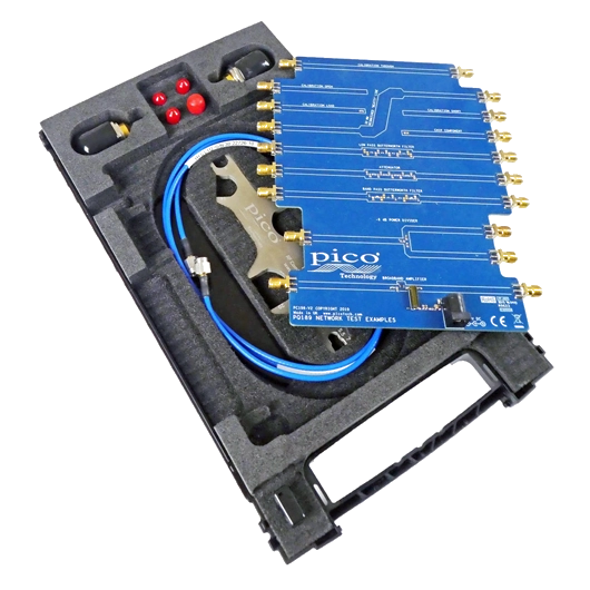
Network Metrology Training kit and carry case
Precision You Can Trust
NABL-Accredited Calibration | Available on Request
The PQ186 Network Metrology Training Kit is an educational RF and VNA measurement package designed for teaching S-parameters, reflection and transmission measurements, SOLT calibration, impedance matching, filters, attenuators, power dividers and active RF circuits. It includes a training PCB, SMA female SOLT kit, test leads, N-to-SMA adaptors, SMA adaptor and PicoWrenches, all organised in a carry case for use with a compatible PicoVNA..
- Detail
- Special Features
- Specification
The Pico PQ186 Network Metrology Training Kit is developed for universities, engineering colleges, RF laboratories, training centres and engineers learning practical vector network analyser measurement techniques.
The kit is centred around the PQ189 Network Metrology Training PCA, a specially designed printed circuit assembly containing passive, active and transmission-line circuits that can be measured using a PicoVNA.
The official PQ186 package includes:
- PQ189 Network Metrology Training PCA
- PQ190 SMA female training SOLT calibration kit
- 2 × N-type male to SMA female inter-series adaptors
- 2 × TA312 60 cm SMA male-to-male test leads
- 1 × TA484 SMA male-to-male adaptor
- 2 × TA486 PicoWrenches
- Carry case
- Network Metrology Training Kit User's Guide and supporting files
The kit is intended to be paired with a PicoVNA. The VNA itself is purchased separately.
Designed for Practical VNA Training
The PQ186 allows students and engineers to perform practical experiments instead of studying RF network analysis only in theory.
Training topics include:
- Reflection measurements
- Transmission measurements
- S-parameters
- Return loss
- Insertion loss
- VSWR
- Smith charts
- Group delay
- Phase measurements
- Time-domain reflection
- Time-domain transmission
- One-port calibration
- Two-port calibration
- SOLT calibration
- Known-through calibration
- Unknown-through calibration
- Reference-plane shifting
- De-embedding
- P1dB compression
- AM-to-PM conversion
Pico specifically developed the kit to support teaching of fundamental network metrology and practical high-frequency measurement techniques.
PQ189 Network Metrology Training PCA
The PQ189 Network Test PCA is the main experimental circuit board supplied with the training kit.
It incorporates more than ten measurement structures and RF circuits.
Examples include:
- Short circuit
- Open circuit
- 50 Ω load
- Through transmission line
- 25 Ω mismatched transmission line
- Attenuator
- Low-pass Butterworth filter
- Band-pass Butterworth filter
- Resistive power divider
- Broadband amplifier
- User-defined 0603 component location
The PCB layout is intentionally generic so educators and students can modify or replace components for additional experiments.
On-Board SOLT Calibration Standards
One end of the training PCA contains transmission-line-based calibration standards for:
- Short
- Open
- Load
- Through
These on-board standards allow students to learn calibration directly at the PCB reference plane.
They can practise:
- Reflection calibration
- Transmission calibration
- Eight-term correction
- Twelve-term correction
- Known-through calibration
- Unknown-through calibration
This is particularly useful for explaining why calibration reference planes matter in high-frequency measurements.
PQ190 SMA Female Training SOLT Kit
The PQ186 also includes a separate PQ190 SMA(f) Training SOLT Calibration Kit.
The PQ190 is a budget training calibration standard designed specifically for educational use with the PQ186 system. Pico also sells it separately as a replacement item if the original is damaged.
The separate SOLT kit allows students to calibrate at the ends of the test cables rather than directly on the training PCB.
This helps demonstrate:
- Cable-end calibration
- Reference-plane movement
- Feed-line effects
- Normalisation
- De-embedding
- Differences between calibration methods
Pico provides assumed ideal and typical calibration data for the training standards so students can explore how calibration-standard errors influence measurement results.
Two TA312 SMA Test Leads
The kit includes two TA312 60 cm SMA male-to-male test leads.
These leads connect the training setup between:
- N-to-SMA adaptors
- Training calibration standards
- Training PCA
- RF devices under test
Two cables are required for complete two-port VNA measurements involving S11, S21, S12 and S22.
The cables are educational working leads rather than premium metrology-grade test cables.
N-Type to SMA Adaptors
PQ186 includes two N-type male to SMA female inter-series adaptors.
These adaptors provide the connection between PicoVNA N-type test ports and the SMA male test leads used throughout the training kit.
The measurement chain typically becomes:
PicoVNA N-type port → N(m)-SMA(f) adaptor → TA312 SMA(m-m) cable → calibration standard or training PCB
This enables students to work with industry-standard SMA measurement interfaces while using PicoVNA hardware.
TA484 SMA Male-to-Male Adaptor
The current official PQ186 product listing includes one TA484 SMA male-to-male adaptor.
It can be used for RF interconnection and calibration exercises where two SMA female interfaces must be joined.
This item should be listed in the RevineTech package specification because it appears in Pico's current official PQ186 contents.
Two TA486 PicoWrenches
The current PQ186 kit includes two TA486 PicoWrenches.
These tools help students learn correct RF connector handling and repeatable tightening practices.
Proper connector handling is important because measurement accuracy can be affected by:
- Loose connectors
- Excessive torque
- Connector wear
- Poor contact repeatability
- Contamination
- Mechanical movement
Including dedicated wrenches helps reinforce good RF measurement practice from the beginning.
25 Ω Mismatched Transmission Line
The training PCB contains a deliberately mismatched transmission line with approximately 25 Ω characteristic impedance.
Students can measure:
- S11
- S21
- Reflection coefficient
- Impedance
- Standing-wave behaviour
- Smith-chart movement
- Transmission loss
The mismatched line demonstrates how a transmission path behaves when its characteristic impedance differs significantly from the nominal 50 Ω measurement system.
Low-Pass Filter Experiment
The PCB includes a Butterworth low-pass filter.
It can be used to demonstrate:
- Passband behaviour
- Cut-off frequency
- Insertion loss
- Stopband attenuation
- Phase response
- Group delay
- Filter S-parameters
Students can compare measured behaviour with theoretical or simulated filter response.
Band-Pass Filter Experiment
A Butterworth band-pass filter is also included.
The circuit can demonstrate:
- Centre frequency
- Passband width
- Lower and upper cut-off frequencies
- Insertion loss
- Return loss
- Out-of-band rejection
- Group delay
This provides a practical introduction to RF filter design and network analysis.
Resistive Power Divider
The training PCA contains a 6 dB resistive power divider.
Students can evaluate:
- Input matching
- Output matching
- Insertion loss
- Isolation
- Power division
- Transmission between ports
This helps explain multi-port RF network behaviour.
Attenuator Measurement
The included attenuator network allows measurements of:
- Insertion loss
- Return loss
- Phase response
- Frequency-dependent attenuation
- Port matching
Students can compare the measured attenuation with its nominal design value.
Broadband Amplifier
The training PCA includes an active broadband amplifier operating up to approximately 6 GHz.
An external +5 V DC supply is required and is not included in the PQ186 kit.
The amplifier can be used to explore:
- Forward gain
- Input return loss
- Output return loss
- Reverse isolation
- Gain flatness
- Compression behaviour
- P1dB
- AM-to-PM conversion
This extends the kit beyond passive network measurements.
P1dB Compression Measurement
When used with a suitable PicoVNA, students can explore the amplifier's 1 dB compression point.
P1dB measurements demonstrate:
- Linear amplifier operation
- Gain compression
- Input power variation
- Output power limitations
- Nonlinear RF behaviour
Pico specifically identifies P1dB as one of the more advanced measurements supported by the training platform.
AM-to-PM Conversion
The active amplifier also allows students to explore AM-to-PM conversion.
This measurement examines how the phase of an RF signal changes as its amplitude varies.
It is useful for understanding:
- Amplifier nonlinearity
- Phase distortion
- Communication-system behaviour
- High-power RF design
Pico identifies AM-to-PM conversion as another advanced experiment available when the training kit is used with a compatible PicoVNA.
User-Defined 0603 Component Position
The PCB includes a location where users can install their own 0603 surface-mount component.
This enables customised experiments involving:
- Resistors
- Capacitors
- Inductors
- Small RF components
- Matching components
- Experimental circuits
Students can measure the component and compare its actual RF behaviour with nominal or simulated values.
Smith Chart Training
The PQ186 is particularly useful for teaching Smith chart interpretation.
Students can display measurements such as:
- Reflection coefficient
- Complex impedance
- Complex admittance
- Return loss
- Matching behaviour
The open, short, load, mismatched line and filter circuits provide several clearly different Smith-chart patterns for practical learning.
Time-Domain Analysis
With PicoVNA software, suitable frequency-domain measurements can be transformed into the time domain.
Training exercises can cover:
- Time-domain reflection
- Time-domain transmission
- Connector discontinuities
- Transmission-line impedance changes
- Electrical length
- Reflection location
- Cable and PCB discontinuities
This helps link conventional S-parameter measurements with transmission-line behaviour.
Reference-Plane Shift and De-Embedding
Using both cable-end and on-board calibration standards allows students to see how the chosen calibration reference plane affects the displayed measurement.
They can explore:
- Cable removal
- Feed-line removal
- Reference-plane extension
- Fixture de-embedding
- Normalisation
- PCB launch effects
This is one of the most useful practical lessons for engineers moving from basic VNA measurements to real RF design work.
PicoVNA Software and Programming Exercises
When paired with a PicoVNA, students can use PicoVNA software for:
- Frequency-domain measurements
- Smith charts
- Polar plots
- Time-domain analysis
- Markers
- Group delay
- Trace comparison
- Calibration
Pico also provides software-development examples so students can explore remote programming and data transfer using environments such as MATLAB, LabVIEW and standard programming languages.
Cadence AWR Microwave Office Integration
Pico provides training PCB design data that can be imported into Cadence AWR Microwave Office.
This enables students to follow a practical:
Design → Simulate → Build → Measure → Compare
workflow.
Measured VNA results can therefore be compared with simulation, which is useful for:
- RF design education
- Filter design
- Transmission-line analysis
- Matching networks
- Component modelling
- Research projects
Pico also highlights this simulation and measurement workflow in its education resources.
Applications
The PQ186 is suitable for:
- RF engineering education
- Vector network analyser training
- University RF laboratories
- Microwave engineering courses
- Electronics training centres
- S-parameter education
- SOLT calibration practice
- Smith chart training
- Transmission-line experiments
- RF filter measurements
- Amplifier characterisation
- P1dB experiments
- AM-to-PM analysis
- PCB network measurements
- VNA programming exercises
- Research and student projects
Why Buy from RevineTech?
RevineTech can supply the Pico PQ186 Network Metrology Training Kit for universities, RF training laboratories, research institutions and engineering teams.
Technical support can include:
- PQ186 training-kit selection
- PicoVNA compatibility
- Training laboratory configuration
- Calibration workflow guidance
- Test-lead and adaptor selection
- Replacement PQ189 or PQ190 components
- RF connector accessories
- Training and measurement setup support
Complete Network Metrology Training Package
The kit includes:
- Training PCB
- Training SOLT standards
- Two SMA test leads
- Two N-to-SMA adaptors
- SMA adaptor
- Two PicoWrenches
- Carry case
- Training documentation
PQ189 Training PCA
Includes example circuits for:
- Short, open, load and through
- 25 Ω mismatched line
- Low-pass filter
- Band-pass filter
- Attenuator
- 6 dB power divider
- Broadband amplifier
- User-defined 0603 component
Two Calibration Methods
Students can practise:
- On-board PCB calibration
- Cable-end calibration using the PQ190 SOLT kit
RF Measurements up to 6 GHz
The training platform is primarily designed for experiments up to 6 GHz when paired with a PicoVNA. Pico's training documentation specifically describes the board and SMA measurement environment as supporting measurements out to 6 GHz.
Active and Passive Networks
The PCB includes:
- Passive components
- Transmission-line structures
- Filters
- Power divider
- Broadband active amplifier
Practical Nonlinear Measurements
With a suitable PicoVNA, the platform supports demonstrations of:
- P1dB compression
- AM-to-PM conversion
Replaceable Training Components
PQ189 and PQ190 are separately available, allowing damaged or heavily used student components to be replaced without purchasing the complete training kit.
| Specification | Details |
|---|---|
| Product name | Network Metrology Training Kit and Carry Case |
| Pico product code | PQ186 |
| Product type | VNA education and network metrology training kit |
| Primary application frequency | Up to 6 GHz |
| Nominal RF system impedance | 50 Ω |
| Training PCB | PQ189 |
| Separate training SOLT kit | PQ190 SMA female |
| VNA-side adaptors | 2 × N male to SMA female |
| Test leads | 2 × TA312, 60 cm SMA male-to-male |
| SMA adaptor | 1 × TA484 SMA male-to-male |
| RF tools | 2 × TA486 PicoWrench |
| Carry case | Included |
| Training documentation | Available |
| PicoVNA instrument | Not included |
PQ189 Training PCA
| Feature | Details |
|---|---|
| Product code | PQ189 |
| Product type | Network metrology training printed circuit assembly |
| Calibration structures | Short, open, load and through |
| Mismatched line | Approximately 25 Ω |
| Filters | Low-pass and band-pass |
| Attenuator | Included |
| Power divider | 6 dB resistive divider |
| Active circuit | Broadband amplifier |
| User experiment site | 0603 component position |
| Amplifier supply | External +5 V DC required |
| External supply included | No |
PQ190 Training SOLT Kit
| Specification | Details |
|---|---|
| Product code | PQ190 |
| Product type | Training manual SOLT calibration kit |
| Connector configuration | SMA female |
| Standards | Short, open, load and through |
| Primary purpose | Cable-end calibration training |
| Replacement availability | Sold separately |
| E-Cal operation | No |