
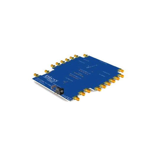
Network Metrology Training printed circuit assembly and carry case
Precision You Can Trust
NABL-Accredited Calibration | Available on Request
The PQ189 Network Metrology Training Printed Circuit Assembly is a practical RF and VNA education accessory for learning S-parameters, SOLT calibration, transmission-line behaviour, filters, attenuation, power division and active-device measurements. The board includes end-of-line short, open, load and through calibration structures, a 25 Ω mismatched line, filters, attenuator, power divider, broadband amplifier and user component test site, supplied with a protective carry case..
- Detail
- Special Features
- Specification
The PQ189 Network Metrology Training Printed Circuit Assembly is designed for practical vector network analyser education, RF laboratory experiments and engineering training.
It is the central printed circuit assembly used in Pico Technology's PQ186 Network Metrology Training Kit and is also available separately. Pico specifically offers PQ189 so a damaged training board can be replaced, or so users who already own suitable test leads and calibration standards can purchase only the training PCA without unnecessary additional accessories.
The training board contains a variety of lumped-element, active, passive and transmission-line devices under test, together with end-of-line SOLT calibration standards.
Practical VNA Training Platform
PQ189 allows students and engineers to move beyond theoretical network-analysis concepts and make practical measurements using a compatible vector network analyser.
The board can be used to explore:
- S11 input reflection
- S21 forward transmission
- S12 reverse transmission
- S22 output reflection
- Return loss
- Insertion loss
- Reflection coefficient
- Impedance
- Phase
- Group delay
- Smith charts
- Time-domain reflection
- Time-domain transmission
- Calibration reference planes
- Transmission-line effects
When paired with a compatible PicoVNA, results can be displayed in logarithmic, linear, phase, real, imaginary, polar and Smith-chart formats.
Integrated SOLT Calibration Structures
The training PCA incorporates end-of-line calibration structures for:
- Short
- Open
- Load
- Through
These structures allow students to practise VNA calibration directly at the printed circuit board reference plane.
Training exercises can demonstrate:
- Reflection calibration
- Transmission calibration
- SOLT calibration
- 8-term correction
- 12-term correction
- Known-through methods
- Unknown-through methods
- Reference-plane positioning
The on-board calibration structures are intended primarily for training and experimentation. They should not be presented as traceable professional calibration standards equivalent to Pico's TA344, TA345, TA346 or TA347 kits.
25 Ω Mismatched Beatty Line
The PQ189 includes a deliberately mismatched 25 Ω Beatty line.
A 25 Ω transmission line connected within a nominal 50 Ω measurement environment creates a significant and predictable impedance discontinuity.
Students can use it to study:
- Reflection coefficient
- Return loss
- Standing waves
- Impedance mismatch
- Transmission response
- Smith-chart behaviour
- Time-domain reflections
- Reference-plane effects
This makes the structure particularly useful for demonstrating how impedance discontinuities appear in both frequency-domain and time-domain VNA measurements.
Low-Pass Butterworth Filter
The board incorporates a low-pass Butterworth filter that can be measured to demonstrate:
- Passband response
- Cut-off frequency
- Insertion loss
- Return loss
- Stopband attenuation
- Phase response
- Group delay
- S-parameter behaviour
Students can compare measured filter behaviour with theoretical calculations or RF simulation results.
Band-Pass Butterworth Filter
An integrated band-pass Butterworth filter provides another practical DUT.
Measurements can include:
- Centre frequency
- Passband width
- Lower cut-off frequency
- Upper cut-off frequency
- Insertion loss
- Return loss
- Out-of-band attenuation
- Phase
- Group delay
Using both low-pass and band-pass structures helps demonstrate how filter topology changes network response.
Attenuator
The training PCA includes an attenuator for practical measurements of:
- Attenuation
- Insertion loss
- Return loss
- Input matching
- Output matching
- Phase response
- Frequency-dependent loss
This provides a straightforward two-port network for introducing transmission measurements before moving to more complex filters and active circuits.
6 dB Resistive Power Divider
The PQ189 includes a −6 dB resistive power divider.
It can be used to investigate:
- Power division
- Insertion loss
- Input matching
- Output matching
- Isolation
- Transmission between ports
- Multi-port RF network behaviour
The circuit helps students understand how RF power is distributed between different network branches.
6 GHz Broadband Amplifier
The training PCA contains an active broadband amplifier designed for experiments extending to approximately 6 GHz.
The amplifier requires an external +5 V DC supply, which is not part of the PQ189 board package.
The amplifier can be used to measure:
- Forward gain
- Reverse isolation
- Input return loss
- Output return loss
- Gain flatness
- Phase response
- Gain compression
- P1dB
- AM-to-PM conversion
When used with suitable PicoVNA measurement functions, the active circuit allows students to progress from linear passive measurements to nonlinear RF characterisation.
P1dB Compression Training
The broadband amplifier enables practical investigation of the 1 dB compression point.
Students can observe how amplifier gain changes as RF input power increases and identify the point at which the amplifier departs from linear operation.
This helps explain:
- Linear gain
- Gain compression
- Input-power dependence
- Output-power limits
- Nonlinear RF behaviour
- Amplifier dynamic range
AM-to-PM Conversion
The active amplifier also supports experiments involving amplitude-to-phase conversion.
AM-to-PM measurements show how changes in signal amplitude can produce corresponding phase changes in a nonlinear RF device.
This is useful for understanding:
- Amplifier nonlinearity
- Phase distortion
- Communication-system performance
- Modulated RF signal behaviour
- Active-device characterisation
Pico specifically identifies P1dB and AM-to-PM as advanced measurements that can be explored using the training platform with a suitable PicoVNA.
User-Defined 0603 Component Test Location
The board includes a test position for a user-selected 0603 surface-mount component.
Users can install components such as:
- Resistors
- Capacitors
- Inductors
- Matching components
- Small RF devices
This allows students to measure the real high-frequency behaviour of a component and compare it with its nominal or simulated characteristics.
It also makes the PQ189 suitable for custom laboratory exercises rather than limiting users to the permanently installed example circuits.
Up to 6 GHz Training Applications
The PQ189 training environment is designed around industry-standard SMA interfaces and practical measurements out to approximately 6 GHz.
This bandwidth is suitable for teaching concepts relevant to:
- RF circuit design
- Wireless electronics
- Microwave engineering
- PCB transmission lines
- RF filters
- Amplifiers
- Matching networks
- Cable and connector measurements
The page should use 6 GHz as the primary application bandwidth for the training PCA, not 8.5 GHz.
Time-Domain Measurements
Frequency-domain VNA measurements can be transformed into time-domain information using compatible PicoVNA software.
The PQ189 can therefore help demonstrate:
- Time-domain reflection
- Time-domain transmission
- Impedance discontinuity location
- Electrical length
- Feedline effects
- Connector discontinuities
- Mismatched transmission lines
- Reflection position
The 25 Ω Beatty line is particularly useful for showing how a known impedance mismatch appears in the time domain.
Reference-Plane and De-Embedding Experiments
The PQ189 includes feedlines between the external SMA connectors and the individual test structures.
Pico supplies measured typical Touchstone files for de-embedding the PCA feedlines.
This allows students to investigate:
- Reference-plane movement
- Feedline removal
- De-embedding
- Normalisation
- Fixture effects
- PCB launch effects
- Calibration location
These exercises help explain why the calibration reference plane can significantly influence RF measurement results.
Design, Simulation and Measurement Comparison
Pico provides supporting training resources that allow measurements from the PQ189 to be compared with RF design and simulation environments.
Students can therefore work through a practical workflow:
Design → Simulate → Measure → Compare
This is useful for:
- RF filter design
- Transmission-line analysis
- Matching networks
- Component modelling
- PCB RF design
- Engineering research
Suitable for Universities and RF Training Laboratories
The PQ189 is suitable for:
- Universities
- Engineering colleges
- Microwave engineering laboratories
- RF training centres
- Electronics laboratories
- Research institutions
- Corporate engineering training
- Student RF projects
It can be used as a shared laboratory resource where students already have access to suitable VNA test cables, adaptors and calibration standards.
Replacement Part for PQ186
Pico officially lists the PQ189 as a replacement part for the PQ186 Network Metrology Training Kit.
This allows institutions to replace:
- A damaged PCA
- A heavily used student board
- A modified experimental board
without purchasing the complete PQ186 package again.
It also allows laboratories that already have suitable RF accessories to purchase the training PCA separately.
What PQ189 Does Not Include
This distinction is important for the RevineTech product page.
The standalone PQ189 does not include the complete accessory set supplied with PQ186.
Do not list the following as standard PQ189 contents:
- PQ190 separate SMA female training SOLT kit
- TA312 test leads
- N-type-to-SMA adaptors
- TA484 adaptor
- TA486 PicoWrenches
- PicoVNA 106
- PicoVNA 108
Those components belong to the complete PQ186 training package or are separately available accessories.
Applications
PQ189 is suitable for:
- Vector network analyser training
- RF engineering education
- S-parameter measurement
- SOLT calibration practice
- Smith-chart training
- Transmission-line experiments
- Impedance mismatch analysis
- RF filter measurements
- Attenuator testing
- Power-divider analysis
- Amplifier characterisation
- P1dB measurement training
- AM-to-PM experiments
- Time-domain analysis
- PCB de-embedding training
- Student projects
- RF research demonstrations
Why Buy from RevineTech?
RevineTech can supply the PQ189 Network Metrology Training PCA for universities, RF laboratories, engineering training centres and research applications.
It is particularly suitable for users who already have a PicoVNA, RF test leads and suitable calibration accessories and want to add a practical network-analysis training platform without purchasing the complete PQ186 kit.
The PQ189 combines several RF training structures on one reusable printed circuit assembly:
- End-of-line short, open, load and through calibration structures
- 25 Ω mismatched Beatty line
- Low-pass Butterworth filter
- Band-pass Butterworth filter
- Attenuator
- −6 dB resistive power divider
- 6 GHz broadband amplifier
- User-defined 0603 component test location
- SMA measurement interfaces
- Support for frequency-domain and time-domain experiments
- De-embedding and reference-plane training
- Protective carry case
| Specification | Details |
|---|---|
| Product name | Network Metrology Training Printed Circuit Assembly and Carry Case |
| Pico product code | PQ189 |
| Product type | VNA / RF network metrology training PCA |
| Primary application bandwidth | Up to 6 GHz |
| Nominal measurement environment | 50 Ω |
| RF interface | SMA |
| Calibration structures | Short, open, load and through |
| Mismatched transmission line | 25 Ω Beatty line |
| Low-pass filter | Butterworth |
| Band-pass filter | Butterworth |
| Attenuator | Included |
| Power divider | −6 dB resistive divider |
| Active DUT | 6 GHz broadband amplifier |
| Amplifier power | External +5 V DC required |
| User component location | 0603 SMD |
| Time-domain training | Supported with compatible VNA |
| Feedline de-embedding | Supported using supplied/downloadable data |
| Carry case | Included |
| PicoVNA | Not included |
Training Structures
| Training Circuit | Primary Measurement Concepts |
|---|---|
| Short | Reflection and SOLT calibration |
| Open | Reflection and SOLT calibration |
| Load | Matching and SOLT calibration |
| Through | Transmission and SOLT calibration |
| 25 Ω Beatty line | Impedance mismatch and reflections |
| Attenuator | Insertion loss and matching |
| Low-pass filter | Passband, cutoff and stopband |
| Band-pass filter | Centre frequency and bandwidth |
| −6 dB power divider | Power division and transmission |
| Broadband amplifier | Gain, return loss and nonlinear behaviour |
| 0603 component site | User-defined RF component measurement |