
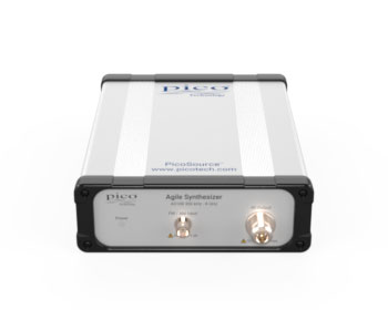
PicoSource™ AS108 8 GHz Agile Synthesizer
Precision You Can Trust
NABL-Accredited Calibration | Available on Request
The PicoSource™ AS108 Agile Synthesizer offers professional-grade performance with a frequency range of 300 kHz to 8 GHz, making it ideal for both benchtop and integrated module applications. With programmable phase, frequency, and amplitude, and remote control via USB, this synthesizer is perfect for developers, educators, and technicians seeking a portable, low-cost solution for testing, modulation, and system integration..
- Detail
- Special Features
- Specification
The PicoSource AS108 Agile Synthesizer is designed for engineers, researchers, service teams, educational laboratories and system integrators who require a compact and programmable RF source.
It is a full-function vector IQ modulating synthesizer that can generate fixed-frequency carrier signals or rapidly change frequency, phase and output level according to a programmed sweep, hop or parameter list.
The instrument provides:
- 300 kHz to 8.192 GHz frequency coverage
- One 50 Ω RF output
- −15 dBm to +15 dBm output power
- Programmable frequency, phase and amplitude
- CW, sweep, hop and arbitrary list modes
- AM, FM and phase modulation
- Internal or external modulation source
- Fast frequency and amplitude settling
- External 10 MHz reference input and output
- Trigger input and output
- Configurable stand-alone power-up mode
- USB control through PicoSynth 2
- API support for automated applications
- Multi-unit operation from one Windows computer
The AS108 is suitable for both conventional bench measurements and integration into automated or unattended RF test systems.
300 kHz to 8.192 GHz Frequency Range
The PicoSource AS108 operates from 300 kHz to 8.192 GHz.
This broad frequency range supports testing of:
- RF amplifiers
- Filters
- Mixers
- Attenuators
- Antennas
- Cables and connectors
- Wireless modules
- Receiver front ends
- Frequency converters
- Communication systems
- Radar and microwave circuits
- Cellular, Bluetooth, Wi-Fi and IoT devices
- Research and educational RF systems
The instrument can be used as a continuous-wave source, a swept source or a rapidly stepped signal generator.
Frequency resolution depends on the selected carrier frequency:
| Frequency Range | Frequency Resolution |
|---|---|
| 300 kHz to 125 MHz | 1 Hz |
| Above 125 MHz to 4 GHz | 10 Hz |
| Above 4 GHz | 20 Hz |
The internal frequency-reference accuracy is specified at ±5 ppm under standard operating conditions.
Adjustable −15 dBm to +15 dBm Output
The AS108 provides an adjustable output level from:
- −15 dBm to +15 dBm
- 0.1 dB setting resolution
- ±1.5 dB specified output-level accuracy
The wide output range allows the same source to be used for:
- Low-level receiver testing
- Filter response measurements
- Amplifier characterisation
- Mixer stimulus
- Sensitivity testing
- Signal-path loss evaluation
- RF module verification
- Educational experiments
External attenuators can be added when lower signal levels or improved source matching are required.
The RF output is protected against up to 25 V DC peak and 20 dBm applied power, but these limits should not be treated as normal operating conditions.
Fast Frequency Settling
The AS108 is designed for parameter-agile applications where frequency must change quickly.
Its frequency settling performance is:
- 55 μs maximum to ±10 ppm
- 50 μs typical to ±10 ppm
Fast settling supports:
- Frequency hopping
- Rapid device testing
- Automated frequency-response measurements
- Multi-band receiver testing
- Production-line RF testing
- Fast stimulus sequencing
- Frequency-agile research systems
The actual complete measurement cycle also depends on trigger configuration, dwell time, connected test equipment and software control.
Fast Amplitude Settling
Output amplitude settling is specified at:
- Less than 25 μs to within ±1 dB
- Less than 200 μs to within ±0.1 dB
This is useful for measurements requiring fast level changes, including:
- Receiver sensitivity tests
- Gain-compression experiments
- Level-dependent amplifier testing
- Automatic gain-control evaluation
- Rapid production screening
- Stepped power-response measurements
Frequency and level can also be varied together during a sweep or list sequence.
CW Signal Generation
In carrier-wave mode, users can directly set:
- Frequency
- Output level
- Carrier phase
- Modulation type
- Modulation depth or deviation
- Output enable state
Values can be entered numerically, scrolled digit by digit or changed using a user-defined increment.
PicoSynth 2 can display output amplitude in several units, including:
- dBm
- mW
- VRMS
- V peak-to-peak
Phase can be entered in degrees or radians.
AM, FM and Phase Modulation
The PicoSource AS108 supports:
- Amplitude modulation
- Frequency modulation
- Phase modulation
Modulation can use:
- An internal sine-wave source
- An external DC-coupled modulation input
The internal modulation generator covers 10 Hz to 5 kHz with 1 Hz resolution.
Key modulation limits include:
| Function | Capability |
|---|---|
| AM depth at 0 dBm carrier | 5% to 90% |
| AM depth from 0 dBm to 9 dBm | 5% to 50% |
| FM deviation | Up to 2% of carrier frequency or 200 kHz |
| Phase modulation deviation | Up to ±180° |
| External modulation bandwidth | DC to 10 kHz |
The external modulation signal is applied through a front-panel BNC input.
Frequency, Level and Phase Sweeps
The AS108 can sweep or hop:
- Frequency
- Output level
- Phase
- Frequency and level together
- Phase and level together
Dual-parameter sweeps are useful when the required output level changes with frequency. For example, level can be increased during a frequency sweep to compensate for test-cable or fixture loss.
A sweep can contain:
- 2 to 10,001 points
- User-defined start and stop values
- Forward or bidirectional operation
- Adjustable dwell time
- Internal, external or software triggering
A hop is a two-point sweep that alternates between two programmed states.
Arbitrary Parameter List Mode
List mode allows users to import a CSV file containing an arbitrary sequence of:
- Frequency and level points
- Phase and level points
Each list point can have a programmed dwell period.
Available list triggering modes include:
- Internal: The sequence runs continuously according to the selected dwell time.
- External Start: One trigger starts the complete list.
- External Step: Each trigger advances the source to the next list point.
List mode can emulate or create stimulus patterns similar to:
- FSK
- ASK
- PSK
- QPSK
- QAM
- Frequency-hopping sequences
- Device calibration tables
- Custom production-test profiles
The AS108 is not a general-purpose arbitrary waveform generator. These schemes are emulated by changing carrier parameters through the programmed list.
Adjustable Sweep Dwell Time
Frequency-step dwell time can be programmed from:
- 27 μs to 65,500 μs
When saving a sequence as the device power-up configuration, the supported range is more limited.
Certain large frequency transitions involving the 7 GHz to 8 GHz region require a minimum dwell of 100 μs.
The chosen dwell time should allow the source and connected measurement instrument to settle before a result is recorded.
Low Phase Noise
Typical phase-noise performance at a 10 kHz offset is:
| Carrier Frequency | Typical Phase Noise |
|---|---|
| 1 GHz | −100 dBc/Hz |
| 2 GHz | −96 dBc/Hz |
| 4 GHz | −90 dBc/Hz |
| 8 GHz | −85 dBc/Hz |
Low phase noise supports:
- Receiver testing
- Local-oscillator simulation
- Clock-source evaluation
- Communication-system testing
- Phase-sensitive measurements
- RF filter and mixer experiments
Phase-noise performance varies with carrier frequency and offset frequency.
Signal Purity
At a +10 dBm output setting, published performance includes:
- Harmonics: −20 dBc maximum, −26 dBc typical
- Subharmonics: −40 dBc maximum, −46 dBc typical
- Non-harmonic spurious signals: −50 dBc maximum, −60 dBc typical
External filtering may still be required for applications needing very high spectral purity or harmonic suppression.
External 10 MHz Reference
The AS108 provides:
- Internal 10 MHz reference output
- External 10 MHz reference input
- ±5 ppm external lock range
The reference connections allow the synthesizer to be synchronised with:
- Vector network analysers
- Oscilloscopes
- Spectrum analysers
- Counters
- Additional signal sources
- Laboratory frequency standards
- Automated RF systems
Using a common reference helps maintain frequency coherence between multiple instruments.
Trigger Input and Output
Rear-panel trigger connections support synchronisation of:
- Sweep start
- Individual sweep points
- Frequency hops
- List sequences
- External measurement instruments
Triggering can be configured to:
- Begin a complete sequence
- Advance to the next point
- Generate a synchronous trigger output
- Coordinate several RF instruments
The typical delay from trigger output to an RF event is approximately:
- 17.5 μs for a frequency or phase step
- 37.5 μs for an output-level step
Trigger timing must be considered when integrating the source into high-speed automated systems.
Stand-Alone Power-Up Mode
A custom operating state can be saved inside the instrument.
This allows the AS108 to power up with a predefined:
- Frequency
- Level
- Phase
- Sweep
- List
- Modulation
- Trigger configuration
After configuration, the instrument can operate in the saved state without continuous USB control.
This is useful for:
- Unattended installations
- Embedded test systems
- Remote stimulus sources
- Production fixtures
- Repetitive demonstrations
- Fixed-frequency laboratory setups
PicoSynth 2 Software
PicoSynth 2 provides a Windows-based interface for controlling the AS108.
Its main operating areas are:
- Carrier wave and basic modulation
- Sweep and hop configuration
- Arbitrary parameter lists
The touchscreen-compatible interface supports:
- Numerical parameter entry
- Digit scrolling
- User-defined increments
- Unit conversion
- Save and recall
- CSV list import
- Trigger configuration
- Demonstration mode
- Multi-device control
Multiple AS108 units can be controlled by running separate PicoSynth 2 instances on the same computer.
API and Automated Control
The AS108 is supplied with a DLL and programming support for custom applications.
Supported development environments include:
- C
- C++
- C#
- Python
- LabVIEW
- MATLAB
- Keysight VEE
Automation can be used for:
- Production testing
- Receiver validation
- Frequency-response measurements
- Automated component testing
- Multi-source systems
- Remote laboratories
- Unattended installations
- Custom RF stimulus generation
The computer communicates with the instrument through USB 2.0.
PicoVNA Integration
The PicoSource AS108 can be used as an externally controlled local oscillator with supported PicoVNA mixer-measurement configurations.
Typical applications include:
- Mixer conversion-loss measurement
- Swept RF or IF tests
- High-side and low-side LO configurations
- Mixer compression analysis
- RF test-system integration
Mixer measurement support depends on the selected PicoVNA model and software version.
Applications
The PicoSource AS108 is suitable for:
- RF component development
- Amplifier and filter testing
- Mixer measurements
- Receiver sensitivity testing
- Frequency-response testing
- Antenna and cable experiments
- Communication-system development
- Local-oscillator simulation
- Frequency-hopping tests
- Automated production testing
- Educational RF laboratories
- Field installation and maintenance
- Radar and microwave research
- Multi-source stimulus systems
- PicoVNA mixer testing
- OEM and system integration
300 kHz to 8.192 GHz Frequency Range
Supports RF stimulus for components and systems operating from low RF frequencies through microwave bands.
−15 dBm to +15 dBm Output
- 30 dB programmable level range
- 0.1 dB setting resolution
- Suitable for receiver, amplifier and passive-component testing
Fast Parameter Settling
- Frequency settling within 55 μs to ±10 ppm
- Amplitude settling within 25 μs to ±1 dB
- Amplitude settling within 200 μs to ±0.1 dB
Sweep, Hop and List Modes
Programmable parameters include:
- Frequency
- Level
- Phase
- Frequency with level
- Phase with level
AM, FM and Phase Modulation
- Internal sine-wave modulation
- External DC-coupled modulation
- AM depth up to 90%
- FM deviation up to 200 kHz or 2% of carrier frequency
- Phase deviation up to ±180°
External Reference and Trigger I/O
- 10 MHz reference input
- 10 MHz reference output
- Trigger input
- Trigger output
- Multi-instrument synchronisation
Stand-Alone Operation
A custom power-up mode can be stored inside the instrument for operation without continuous USB control.
PicoSynth 2 Software
- Touch-compatible interface
- CW, modulation, sweep, hop and list controls
- CSV list import
- Multiple-device operation
- Demonstration mode
Programming Support
Examples and API support are available for C, C++, C#, Python, LabVIEW and MATLAB.
Core Technical Specifications
| Specification | PicoSource AS108 |
|---|---|
| Product type | USB-controlled vector IQ signal synthesizer |
| RF output channels | 1 |
| Frequency range | 300 kHz to 8.192 GHz |
| Output impedance | 50 Ω |
| RF output connector | N-type female |
| Output power range | −15 dBm to +15 dBm |
| Output power resolution | 0.1 dB |
| Output power accuracy | ±1.5 dB |
| Internal frequency accuracy | ±5 ppm |
| Maximum frequency settling | 55 μs to ±10 ppm |
| Maximum amplitude settling | 25 μs to ±1 dB |
| Maximum fine amplitude settling | 200 μs to ±0.1 dB |
| Modulation | AM, FM and PM |
| Operating modes | CW, sweep, hop and list |
| Control interface | USB 2.0 |
| Software | PicoSynth 2 |
| API control | Included |
| Power requirement | 12 V to 15 V DC |
| Warranty | Three years |
Frequency Specifications
| Frequency Range | Resolution |
|---|---|
| 300 kHz to 125 MHz | 1 Hz |
| Above 125 MHz to 4 GHz | 10 Hz |
| Above 4 GHz to 8.192 GHz | 20 Hz |
Phase-Noise Specifications
| Carrier Frequency | Maximum at 10 kHz Offset | Typical at 10 kHz Offset |
|---|---|---|
| 1 GHz | −98 dBc/Hz | −100 dBc/Hz |
| 2 GHz | −94 dBc/Hz | −96 dBc/Hz |
| 4 GHz | −88 dBc/Hz | −90 dBc/Hz |
| 8 GHz | −83 dBc/Hz | −85 dBc/Hz |
Sweep and List Specifications
| Specification | Details |
|---|---|
| Programmable parameters | Frequency, level, phase, frequency and level, phase and level |
| Sweep or list points | 2 to 10,001 |
| Stored power-up sequence points | Up to 1,750 |
| Standard dwell-time range | 27 μs to 65,500 μs |
| Hop mode | Two-point sweep |
| Bidirectional sweep | Supported |
| CSV parameter lists | Supported |
| Triggered start | Supported |
| Triggered next point | Supported |
Modulation Specifications
| Specification | Details |
|---|---|
| Modulation types | AM, FM and PM |
| Internal modulation waveform | Sine |
| Internal frequency range | 10 Hz to 5 kHz |
| Internal frequency resolution | 1 Hz |
| Internal frequency accuracy | ±0.1% |
| AM depth at 0 dBm | 5% to 90% |
| FM deviation | Up to 2% of carrier frequency or 200 kHz |
| PM deviation | ±180° |
| External modulation bandwidth | DC to 10 kHz |
| External modulation connector | BNC female |
| External input sensitivity | Approximately ±1 V peak |
| External input protection | ±5 V DC plus AC peak |
Synchronisation Specifications
| Specification | Details |
|---|---|
| Internal reference output | 10 MHz |
| Reference output level | 0 dBm typical into 50 Ω |
| External reference input | 10 MHz |
| External reference sensitivity | −6 dBm |
| Maximum reference input | +6 dBm |
| External reference lock range | ±5 ppm |
| Trigger input connector | BNC female |
| Trigger output connector | BNC female |
| Trigger output rise/fall time | 40 ns maximum |
| Frequency or phase event delay | 17.5 μs typical |
| Level event delay | 37.5 μs typical |
Output Signal Quality
| Specification | Maximum | Typical |
|---|---|---|
| Output VSWR | 1.8:1 | 1.4:1 |
| Harmonics at +10 dBm | −20 dBc | −26 dBc |
| Subharmonics at +10 dBm | −40 dBc | −46 dBc |
| Non-harmonic spurious at +10 dBm | −50 dBc | −60 dBc |
Software and Automation
| Function | Capability |
|---|---|
| Control software | PicoSynth 2 |
| Supported operating system | Microsoft Windows |
| Carrier control | Frequency, phase and level |
| Sweep and hop control | Included |
| CSV list import | Included |
| Multiple AS108 units | Supported |
| Demonstration mode | Included |
| Stand-alone power-up state | User configurable |
| API and DLL | Included |
| Programming examples | C, C++, C#, Python, LabVIEW and MATLAB |
Physical and Environmental Specifications
| Specification | Details |
|---|---|
| Dimensions | 173 × 232 × 56 mm, excluding connectors |
| Weight | Approximately 1.78 kg |
| Power input | 12 V to 15 V DC |
| Maximum power consumption | Approximately 12 W |
| Operating temperature | 5°C to 40°C |
| Operating humidity | Up to 80% RH, non-condensing |
| Storage temperature | −20°C to 50°C |
| Control connection | USB 2.0 |