
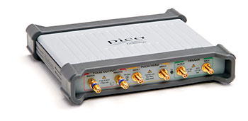
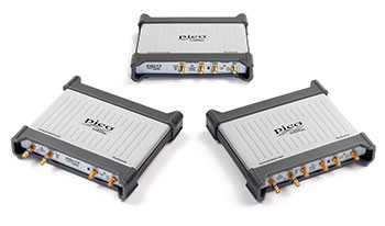
PicoSource PG900 Series
Precision You Can Trust
NABL-Accredited Calibration | Available on Request
The PicoSource PG900 Series is a range of low-jitter, USB-controlled differential pulse generators designed for TDR, TDT, semiconductor testing, gigabit interconnect analysis and fast-response measurements. Depending on the model, it provides less than 60 ps step-recovery-diode transitions with adjustable 2.5 V to 6 V outputs, or less than 40 ps tunnel-diode transitions with fixed 200 mV outputs. Programmable pulse width, repetition rate, trigger control and 1 ps deskew support precise high-speed testing..
- Detail
- Special Features
- Specification
The PicoSource PG900 Series USB Pulse Generators produce fast positive-going and negative-going pulses for stimulating high-bandwidth devices, transmission paths and electronic systems.
The series is designed for engineers, research laboratories, semiconductor developers, communications teams and test-system integrators who need a portable source with picosecond transition times and accurate differential timing control.
Depending on the selected model, the series provides:
- Integrated step-recovery-diode pulse outputs
- Remote tunnel-diode pulse heads
- Less than 60 ps or less than 40 ps transition time
- Differential positive and negative outputs
- Up to 12 V peak differential drive using SRD outputs
- Programmable pulse amplitude on SRD models
- Adjustable pulse width and repetition period
- 1 ps output deskew increments
- Internal clock operation
- External trigger input and output
- Manual single-shot triggering
- USB control through PicoSource PG900 software
- Programmer interface for automated testing
The fast transition produces broad spectral content, allowing one pulse to stimulate a wide frequency range. This makes the PG900 Series useful for time-domain reflectometry, transmission testing, port evaluation and dynamic-response measurements.
PicoSource PG900 Model Range
| Model | Output Technology | Output Channels | Transition Time | Output Amplitude |
|---|---|---|---|---|
| PicoSource PG911 | Integrated step-recovery diode | 2 | Less than 60 ps | Adjustable 2.5 V to 6 V |
| PicoSource PG912 | Remote tunnel-diode pulse heads | 2 | Less than 40 ps | Fixed 200 mV |
| PicoSource PG914 | Step-recovery diode and tunnel diode | 4 | Less than 60 ps SRD; less than 40 ps TD | 2.5 V to 6 V SRD; fixed 200 mV TD |
The official PG900 product configurator still displays PG911, PG912 and PG914. However, Pico Technology’s newer quick-start guide identifies the PG912 as no longer available. RevineTech should confirm current PG912 availability before presenting it as an orderable model.
Differential Picosecond Pulse Generation
The PG900 Series generates complementary positive-going and negative-going pulses for differential testing.
Differential outputs are useful for examining:
- USB interfaces
- SATA links
- HDMI connections
- Ethernet systems
- Differential PCB traces
- High-speed connectors
- Balanced transmission lines
- Differential amplifiers
- Semiconductor input structures
- High-speed cable assemblies
Using matched positive and negative outputs allows engineers to stimulate both sides of a differential path and observe timing, impedance and transmission behaviour.
The PG900 software also allows the two outputs to be deskewed in 1 ps increments. Deskew compensates for cable-length differences, connector delays and unequal signal paths. It can also introduce controlled skew deliberately for stress testing.
Step-Recovery-Diode Outputs
The PicoSource PG911 and PG914 include integrated step-recovery-diode, or SRD, outputs.
Their main capabilities include:
- Positive-going and negative-going pulses
- 50 Ω output impedance
- SMA female connectors
- Adjustable amplitude from 2.5 V to 6 V
- 10 mV amplitude-setting increments
- Adjustable output-amplitude limit
- Less than 60 ps transition time in smooth mode
- Less than 50 ps negative-going transition in fast mode
- Differential deskew adjustment in 1 ps steps
- 20 dB, 10 GHz attenuators supplied on the SRD outputs
Each output can deliver up to 6 V peak into 50 Ω. Used together, the complementary channels can create up to 12 V peak differential amplitude. This higher drive level is useful for lossy transmission paths, device-port stress tests and general high-speed component evaluation.
Adjustable SRD Output Amplitude
SRD amplitude can be programmed from:
- 2.5 V to 6 V
- In 10 mV setting increments
An amplitude limit can be configured from 2.5 V to 6 V in 100 mV increments. This helps prevent accidental application of excessive pulse amplitude to a sensitive device.
The stated output accuracy is approximately ±10% under the specified operating and calibration conditions.
SRD Duty-Cycle Limits
The permitted duty cycle depends on the selected output amplitude:
- Up to 50% for amplitudes from 2.5 V to 4 V
- Up to 20% for amplitudes above 4 V and up to 6 V
These limits should be followed to avoid exceeding the output-stage operating conditions.
Tunnel-Diode Pulse Heads
The PicoSource PG912 and PG914 support remote tunnel-diode, or TD, pulse heads.
The pulse-head system includes:
- PS9040 positive tunnel-diode pulse head
- PS9041 negative tunnel-diode pulse head
- Less than 40 ps transition time
- Fixed nominal 200 mV output amplitude
- 50 Ω output impedance
- N-type male output connectors
- Independent differential timing adjustment
- Compact remote pulse-head construction
The remote heads can be placed close to the device under test, reducing the cable length after the fast-transition device. This helps preserve pulse fidelity and reduces additional loss, dispersion and reflection.
Positive and Negative TD Pulses
The PS9040 generates a positive-going fast transition, while the PS9041 generates a negative-going fast transition.
Both provide:
- Fixed 200 mV nominal amplitude
- Less than 40 ps 10% to 90% transition time
- Less than 8 ns trailing-edge transition time
- Adjustable relative timing
- 50 Ω source impedance
The pulse heads are suited to small-signal broadband testing where transition speed is more important than high output amplitude.
Pulse Width Control
All PG900 models provide an adjustable pulse width from:
- 200 ns to 4 µs
- In 25 ns setting increments
Published pulse-width accuracy is:
- ±10%
- Plus or minus 50 ns
Pulse width can be selected according to the transmission path, trigger timing and required measurement window.
Internal Clock and Repetition Rate
The internal clock period is adjustable from:
- 1 µs to 1 second
This corresponds to an internal repetition rate from:
- 1 Hz to 1 MHz
Internal-clock operation allows the generator to run continuously without a separate trigger source.
Typical applications include:
- Continuous TDR stimulus
- Oscilloscope response testing
- Repetitive component evaluation
- Automated manufacturing tests
- Demonstration and training setups
- Repetitive semiconductor measurements
The clock period can be adjusted in 200 ns increments, subject to the instrument’s timing range.
Internal, External and Manual Trigger Modes
The PG900 Series supports three principal trigger sources:
- Internal clock
- External trigger input
- Manual single-shot event
This provides flexibility for free-running tests, synchronised systems and manually initiated measurements.
External Trigger Input
The external trigger input provides:
- 50 Ω impedance
- SMA female connector
- DC-coupled input
- Approximately 1 GHz bandwidth
- Selectable rising or falling trigger edge
- Trigger-level setting from −1 V to +1 V
- 1 mV trigger-level increments
- Adjustable hold-off
The maximum permitted trigger input is +16 dBm or ±2 V DC or AC peak.
Trigger Sensitivity
Published external-trigger sensitivity is:
- Less than 50 mV peak-to-peak from DC to 100 MHz
- Increasing linearly to 100 mV peak-to-peak at 1 GHz
The minimum specified trigger pulse width is 500 ps at 100 mV peak-to-peak.
Low-Jitter Operation
Low timing jitter helps maintain sharp and repeatable waveform alignment during averaging, TDR analysis and high-speed pulse measurements.
Published performance includes:
- Pulse jitter relative to the trigger leading edge of approximately 3 ps RMS typical
- Approximately 3.5 ps RMS maximum
- Trigger-output jitter of approximately 2.5 ps RMS typical
- Approximately 3 ps RMS maximum
Low jitter is important for:
- Picosecond transition measurement
- TDR and TDT analysis
- Oscilloscope bandwidth verification
- High-speed interconnect testing
- Clock-path testing
- Semiconductor switching analysis
- Repetitive waveform averaging
External Trigger Output
The external trigger output can synchronise an oscilloscope or other measurement instrument with the generated pulse.
Its published characteristics include:
- 50 Ω output impedance
- SMA female connector
- Positive-edge trigger pulse
- More than 700 mV fixed amplitude
- Approximately 500 ns pulse width
- Approximately 4 ns trigger-to-output delay
- Less than 400 ps transition time
The output trigger occurs before the generated pulse, allowing a sampling oscilloscope to prepare for the fast event. The generated pulse follows the trigger by approximately 42 ns.
Differential Deskew
Accurate differential testing requires the positive and negative signal paths to arrive at the device under test at the intended relative time.
The PG900 Series allows independent pulse timing to be adjusted in 1 ps increments.
Deskew can be used to:
- Compensate for unequal cable lengths
- Correct adaptor and connector delay
- Align complementary differential transitions
- Match positive and negative test paths
- Introduce controlled skew for tolerance testing
- Evaluate receiver response to differential timing errors
- Test interconnect timing margin
The SRD outputs provide adjustment across a 2 ns total range. The latest data sheet gives a wider model-dependent deskew range for the tunnel-diode configuration than some earlier web specifications, so the applicable firmware and model documentation should be checked for a quoted PG912 or PG914 system.
Time-Domain Reflectometry
A fast pulse contains broad frequency content and can be used as the source for time-domain reflectometry.
In a TDR setup, the pulse is applied to a cable, connector, PCB trace or transmission path. Reflections are captured by a high-bandwidth sampling oscilloscope.
TDR can help identify:
- Impedance discontinuities
- Damaged cable sections
- Connector faults
- Open circuits
- Short circuits
- PCB trace transitions
- Via and package discontinuities
- Incorrect termination
- Distance to an electrical fault
- Differential impedance imbalance
The PG900 Series can be used with PicoScope 9300 Series sampling oscilloscopes and suitable TDR accessories.
Time-Domain Transmission Testing
Time-domain transmission, or TDT, measures the pulse after it passes through a device or transmission path.
TDT can evaluate:
- Insertion behaviour
- Propagation delay
- Pulse distortion
- Rise-time degradation
- Overshoot and ringing
- Differential skew
- Loss and dispersion
- Crosstalk
- Connector and cable performance
- PCB interconnect quality
TDR and TDT together provide complementary information about reflections and transmitted signal quality.
Oscilloscope and Amplifier Response Testing
The fast transition of the PG900 Series can be used to evaluate the step response of:
- High-bandwidth oscilloscopes
- Sampling oscilloscopes
- Amplifiers
- Optical receivers
- Broadband probes
- RF signal paths
- Data-acquisition front ends
- Semiconductor devices
Measured rise time, overshoot, ringing and settling behaviour can reveal bandwidth limits and response abnormalities in the device under test.
Semiconductor and Component Testing
The PG900 Series can stimulate electronic components with repeatable fast pulses.
Applications include:
- Diode switching tests
- Transistor response measurements
- Semiconductor input testing
- Comparator response evaluation
- Logic-gate stress testing
- Package and bond-wire analysis
- Electro-optical component testing
- High-speed component characterisation
- Protection-device response testing
SRD models provide higher amplitude for port and device stress testing, while TD pulse heads provide faster, lower-amplitude transitions for small-signal response measurements.
Gigabit Interconnect Testing
Differential high-speed interconnects can be evaluated for:
- Rise-time degradation
- Differential skew
- Reflections
- Impedance mismatch
- Pulse distortion
- Crosstalk
- Transmission delay
- Connector behaviour
- Cable performance
- PCB routing quality
Applicable systems include USB 3, SATA, HDMI and Ethernet-style differential paths.
Radar and Wideband Pulse Applications
The broad spectral content and precise triggering make the PG900 Series suitable for:
- Radar system development
- Ultra-wideband impulse networks
- Pulse-response testing
- Wideband receiver evaluation
- Antenna impulse testing
- Timing-reference systems
- Research pulse experiments
The instrument can act as a step source for an ultra-wideband impulse-forming network.
USB-Controlled Operation
The instrument connects to a computer through USB 2.0 and is compatible with USB 1.1 and USB 3.0 host ports.
PC-based operation provides:
- Direct numerical control
- Pulse amplitude adjustment
- Pulse width selection
- Repetition-period control
- Output deskew
- Trigger configuration
- Configuration save and recall
- Automated control
- Compact test-system integration
The generator uses an external 5 V DC power adaptor rather than drawing its operating power entirely through USB.
PicoSource PG900 Control Software
The supplied PicoSource software controls:
- Output amplitude
- Output polarity
- Pulse width
- Repetition period
- Differential deskew
- Trigger source
- Trigger edge
- Trigger threshold
- Trigger hold-off
- Single-shot operation
The software provides an accessible alternative to operating a conventional rack-mounted pulse generator through front-panel menus.
Programmer Interface and Automated Testing
Pico Technology provides a programmer’s guide for integrating the PG900 Series into automated systems.
Automated applications may include:
- Production-line pulse testing
- Repetitive component characterisation
- Cable and connector screening
- Semiconductor validation
- Automated TDR/TDT systems
- Remote laboratories
- Custom research instruments
- OEM test equipment
The exact supported programming environment should be checked against the current driver package and programmer documentation before being listed on the product page.
Applications
The PicoSource PG900 Series is suitable for:
- Time-domain reflectometry
- Time-domain transmission testing
- PCB interconnect analysis
- Cable and connector testing
- Differential impedance testing
- Semiconductor characterisation
- High-speed component testing
- Gigabit interface testing
- USB, SATA, HDMI and Ethernet path evaluation
- Oscilloscope response testing
- Amplifier step-response testing
- Electro-optical component testing
- Radar pulse testing
- Ultra-wideband research
- Production-line validation
- Educational and research laboratories
Picosecond Transition Times
Depending on the model:
- Less than 60 ps from integrated SRD outputs
- Less than 50 ps in the SRD negative fast mode
- Less than 40 ps from remote tunnel-diode pulse heads
Differential Pulse Outputs
- Complementary positive and negative pulses
- Differential interconnect stimulus
- Adjustable relative output timing
- Suitable for balanced and single-ended testing
Up to 12 V Peak Differential Drive
PG911 and PG914 SRD outputs provide:
- Up to 6 V peak per output
- Up to 12 V peak differential amplitude
- 2.5 V to 6 V programmable range
- 10 mV amplitude increments
200 mV Tunnel-Diode Outputs
PG912 and PG914 TD pulse heads provide:
- Fixed 200 mV output
- Less than 40 ps transition
- Remote placement near the device under test
- Positive and negative pulse heads
One-Picosecond Deskew Control
- Compensates for unequal signal paths
- Aligns differential outputs
- Introduces deliberate timing skew
- Supports differential tolerance testing
Adjustable Pulse Timing
- Pulse width from 200 ns to 4 µs
- Internal period from 1 µs to 1 second
- Repetition rate from 1 Hz to 1 MHz
Flexible Triggering
- Internal clock
- External trigger
- Manual single shot
- Selectable trigger polarity
- Adjustable trigger level
- Trigger output for measurement-system synchronisation
Low-Jitter Performance
- Pulse jitter around 3 ps RMS typical
- Trigger-output jitter around 2.5 ps RMS typical
- Suitable for repetitive averaging and timing analysis
USB-Controlled Compact Design
- PC-based pulse control
- Compact 560 g instrument
- Automated test support
- External 5 V power adaptor
Core Series Specifications
| Specification | PicoSource PG900 Series |
|---|---|
| Product type | Differential USB picosecond pulse generator |
| Current model family | PG911, PG912 and PG914 shown by configurator |
| Output technologies | Step-recovery diode and tunnel diode |
| SRD transition time | Less than 60 ps |
| SRD fast negative transition | Less than 50 ps |
| TD transition time | Less than 40 ps |
| SRD output amplitude | Adjustable 2.5 V to 6 V |
| TD output amplitude | Fixed 200 mV nominal |
| Output impedance | 50 Ω |
| Pulse width | 200 ns to 4 µs |
| Internal clock period | 1 µs to 1 second |
| Repetition rate | 1 Hz to 1 MHz |
| Deskew resolution | 1 ps |
| Trigger modes | Internal, external and manual |
| PC interface | USB 2.0 |
| Power | External 5 V DC adaptor |
| Warranty | Five years |
Model Comparison
| Model | Outputs | Output Technology | Transition Time | Amplitude |
|---|---|---|---|---|
| PG911 | 2 | Integrated SRD | Less than 60 ps | 2.5 V to 6 V |
| PG912 | 2 | Remote TD heads | Less than 40 ps | Fixed 200 mV |
| PG914 | 4 | Integrated SRD plus remote TD | Less than 60 ps SRD; less than 40 ps TD | 2.5 V to 6 V SRD; 200 mV TD |
Pico’s current quick-start guide marks PG912 as no longer available, so availability should be confirmed before quotation.
Step-Recovery-Diode Output Specifications
| Specification | PG911 and PG914 |
|---|---|
| Output types | Positive-going and negative-going |
| Output impedance | 50 Ω |
| Connector | SMA female |
| Amplitude | 2.5 V to 6 V |
| Amplitude resolution | 10 mV |
| Amplitude accuracy | ±10% |
| Programmable amplitude limit | 2.5 V to 6 V in 100 mV increments |
| Smooth-mode transition | Less than 60 ps |
| Negative fast-mode transition | Less than 50 ps |
| Differential deskew | 1 ps steps across a 2 ns range |
| Maximum duty cycle at 2.5 V to 4 V | 50% |
| Maximum duty cycle above 4 V | 20% |
| Output protection | ±10 V DC or AC peak |
Tunnel-Diode Output Specifications
| Specification | PG912 and PG914 |
|---|---|
| Pulse heads | PS9040 positive and PS9041 negative |
| Output impedance | 50 Ω ±2 Ω |
| Connector | N-type male |
| Output amplitude | Fixed 200 mV nominal |
| Output accuracy | ±25% |
| Transition time | Less than 40 ps |
| Trailing-edge transition | Less than 8 ns |
| Deskew resolution | 1 ps |
| Pulse-head dimensions | Approximately 80 × 28 × 25 mm |
| Pulse-head weight | Approximately 125 g each |
Pulse Timing Specifications
| Specification | Details |
|---|---|
| Trigger source | Internal clock, external input or manual single shot |
| Pulse jitter | 3 ps RMS typical, 3.5 ps maximum |
| Trigger-to-pulse delay | Approximately 42 ns |
| Pulse width | 200 ns to 4 µs |
| Pulse-width adjustment | 25 ns steps |
| Pulse-width accuracy | ±10% ±50 ns |
| Internal clock period | 1 µs to 1 second |
| Internal clock accuracy | ±100 ppm ±10 ns |
| Clock-period step | 200 ns |
External Trigger Input
| Specification | Details |
|---|---|
| Input impedance | 50 Ω ±1% |
| Connector | SMA female |
| Bandwidth | 1 GHz, DC coupled |
| Trigger polarity | Rising or falling |
| Trigger level | −1 V to +1 V |
| Trigger-level resolution | 1 mV |
| Maximum input | +16 dBm or ±2 V DC/AC peak |
| Minimum pulse width | 500 ps at 100 mV peak-to-peak |
| Hold-off | Adjustable |
External Trigger Output
| Specification | Details |
|---|---|
| Output impedance | 50 Ω ±0.5 Ω |
| Connector | SMA female |
| Polarity | Positive edge |
| Output amplitude | More than 700 mV |
| Pulse width | Approximately 500 ns |
| Trigger delay | Approximately 4 ns |
| Jitter | 2.5 ps RMS typical; 3 ps maximum |
| Transition time | Less than 400 ps |
Physical and Environmental Specifications
| Specification | Details |
|---|---|
| Instrument dimensions | Approximately 190 × 180 × 40 mm |
| Instrument weight | Approximately 560 g |
| Power adaptor | 5 V ±5%, 1.6 A |
| Maximum power | Approximately 8 W |
| PC connection | USB 2.0 |
| USB compatibility | USB 1.1 and USB 3.0 host compatible |
| Operating temperature | 5°C to 40°C in the latest data sheet |
| Storage temperature | −20°C to 50°C |
| Maximum altitude | 2,000 m |
| Ingress protection | IP20 |
| Recommended calibration cycle | 12 months |
| Warranty | Five years |