
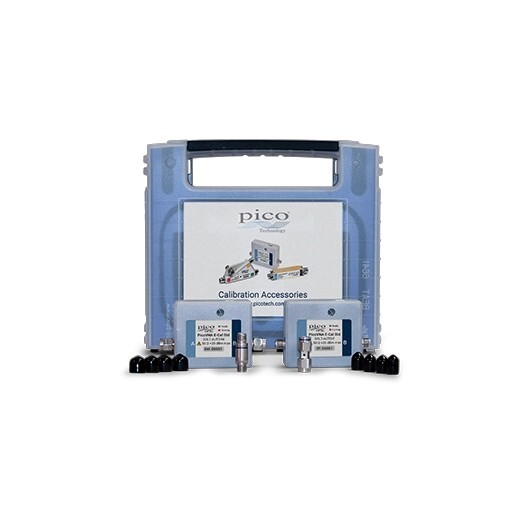
PicoVNA Dual E-Cal 8.5 GHz Automated calibration kit (SMA)
Precision You Can Trust
NABL-Accredited Calibration | Available on Request
The PicoVNA Dual E-Cal TA520 is an automated two-port SOLT calibration kit containing separate SMA male and SMA female E-Cal modules. It covers 300 kHz to 8.5 GHz with 50 Ω interfaces and internally switched short, open, load and through standards. USB power and control, oven-stabilised operation and embedded traceable characterisation data support fast, repeatable PicoVNA calibration with fewer manual RF connections..
- Detail
- Special Features
- Specification
The PicoVNA Dual E-Cal 8.5 GHz Automated Calibration Kit is designed to simplify and improve two-port vector network analyser calibration.
The TA520 kit contains:
- TA518 SOLT-AUTO-M with two SMA male ports
- TA519 SOLT-AUTO-F with two SMA female ports
- Short, open, load and through standards within each module
- A separately characterised and polarised port adaptor
- Embedded full S-parameter characterisation data
- USB power, control and data communication
- Oven-controlled temperature stabilisation
- Protective carrying case
Together, the male and female E-Cal modules support calibration for a wider range of test cables, adaptors, fixtures and devices than a single connector configuration.
Automated SOLT Calibration
A conventional manual SOLT calibration normally requires the operator to connect several individual standards to each VNA port.
These operations may include:
- Connecting the open standard
- Connecting the short standard
- Connecting the load standard
- Connecting the through connection
- Applying the correct connector torque
- Loading characterisation data
- Repeating the process for both ports
Each additional connection introduces a possibility of:
- Incorrect standard selection
- Connector wear
- Inconsistent torque
- Contamination
- Loose connections
- Port or cable movement
- Operator error
The TA520 E-Cal kit reduces the process to a single RF connection for the selected male or female module. PicoVNA software then switches between the internal standards automatically and reads the module’s stored characterisation data over USB.
Dual Male and Female SMA Configuration
The TA520 is a dual kit containing two independent calibration modules.
| Module | Order Code | Connector Configuration |
|---|---|---|
| SOLT-AUTO-M | TA518 | Two SMA male ports |
| SOLT-AUTO-F | TA519 | Two SMA female ports |
The dual configuration is useful when the laboratory regularly measures devices or fixtures with different connector genders.
Typical measurement setups include:
- SMA male-to-male test cables
- SMA female-to-female devices
- Male-to-female RF components
- Insertable devices
- Non-insertable devices
- RF test fixtures
- PCB test fixtures
- Cable assemblies
- Filters and amplifiers
- Antennas and matching networks
The TA520 should not be described simply as one device with interchangeable male and female connectors. It is a kit containing two separately characterised E-Cal modules.
300 kHz to 8.5 GHz Frequency Coverage
Both E-Cal modules are characterised from:
- 300 kHz to 8.5 GHz
This frequency range covers the full measurement bandwidth of current PicoVNA instruments operating below 8.5 GHz and supports common RF applications involving:
- Cellular systems
- Wi-Fi
- Bluetooth
- GNSS
- RFID
- IoT devices
- Sub-GHz communications
- RF filters
- Amplifiers
- Antennas
- Cables and connectors
- PCB transmission lines
- Wireless modules
The calibration frequency range should be presented as 300 kHz to 8.5 GHz, not simply 8.5 GHz.
Internal Short, Open, Load and Through Standards
Each E-Cal module contains electronically switched calibration states representing:
- Short
- Open
- Load
- Through
These standards allow PicoVNA software to calculate systematic measurement-error corrections for a two-port VNA setup.
SOLT calibration can correct errors associated with:
- Directivity
- Source match
- Load match
- Reflection tracking
- Transmission tracking
- Crosstalk or isolation
- Forward measurement paths
- Reverse measurement paths
The correction is applied at the selected calibration reference planes so the displayed results more accurately represent the connected device under test.
Full S-Parameter Characterisation
Electronic standards cannot produce perfectly ideal open, short, load and through responses because internal switches, transmission paths and connectors introduce small imperfections.
Pico reduces their effect by characterising the complete RF behaviour of each module across the full operating frequency span.
The stored characterisation includes multipath S-parameter data for the internal states. PicoVNA software reads this data directly from the module through USB and uses it during calibration.
This approach compensates for the actual measured behaviour of the E-Cal module rather than treating every internal standard as mathematically ideal.
Oven-Controlled Temperature Stabilisation
Each TA518 and TA519 module includes an internal oven system that stabilises the temperature of the RF calibration standards.
Published operating details include:
- Controlled temperature range from 18°C to 28°C for quoted accuracy
- Typical warm-up time of approximately 45 seconds at 23°C
- Operating temperature range from 5°C to 40°C
Temperature stabilisation helps reduce changes in the electrical response of the internal switches, transmission paths and standards.
This supports:
- Better calibration repeatability
- More consistent S-parameter measurements
- Reduced temperature-related drift
- Reliable repeated calibration
- Improved production-test consistency
The module should be allowed to complete its warm-up process before calibration is started.
USB Power, Control and Data
The E-Cal modules use a USB 2.0 Micro connection for:
- Electrical power
- Module control
- Internal standard switching
- Characterisation-data transfer
- Device identification
A separate external power adaptor is not required for each E-Cal module.
The USB connection does not carry the RF measurement signal. RF measurements pass through the two SMA calibration ports, while USB manages the module’s control and stored reference data.
Traceable Calibration Data
Pico Technology states that its VNA calibration and check standards are calibrated against fully traceable PC3.5 standards.
The E-Cal modules are supplied with their characterisation data embedded in internal memory, allowing PicoVNA software to identify the device and apply its individual calibration information automatically.
Traceable characterisation supports applications such as:
- RF research
- Product development
- Production testing
- Quality assurance
- Calibration verification
- Measurement laboratories
- University laboratories
- Telecom component testing
- Automated RF validation
A separate NABL calibration certificate should be mentioned only if RevineTech confirms that it is included within its own commercial package. Pico’s official TA520 product page states traceability to PC3.5 standards but does not identify an NABL certificate as a standard manufacturer inclusion.
Calibration Performance
The individual TA518 and TA519 modules provide the following published calibration performance:
- Directivity: 40 dB
- Source match: 40 dB
- Load match: 36 dB
- Reflection tracking: 0.05 dB
- Transmission tracking: 0.04 dB
These specifications describe the residual calibration performance associated with the characterised E-Cal module under the stated operating conditions.
Measurement performance in a complete setup also depends on:
- VNA model
- Test cable quality
- Connector condition
- Cable movement
- Frequency range
- Measurement bandwidth
- Device mismatch
- Calibration reference plane
- Environmental stability
Port Power Limits
Each E-Cal module has published RF port limits of:
- +10 dBm maximum normal operating input
- +20 dBm or 1 V peak protection limit
The protection rating should not be treated as a normal operating level.
Before calibration, the VNA source power should be checked to ensure that it remains within the specified operating limit.
Calibration Workflow
A typical automated calibration process includes:
- Allow the PicoVNA, test cables and E-Cal module to stabilise.
- Inspect and clean the SMA connectors.
- Select the required TA518 male or TA519 female module.
- Connect the module to the two VNA reference planes.
- Apply the correct SMA connector torque.
- Connect the module to the computer through USB.
- Start the E-Cal procedure in PicoVNA software.
- Allow the software to identify the module and read its stored data.
- Permit the module to switch automatically between its standards.
- Complete and save the calibration.
- Disconnect the E-Cal module and connect the device under test.
- Use a suitable check standard where independent validation is required.
The E-Cal module automates the standards, but correct connector handling, cable positioning and reference-plane selection remain essential.
Reduced Connector Operations
One of the principal benefits of E-Cal is the reduction in repeated connect and disconnect operations.
Fewer connections can help:
- Reduce calibration time
- Minimise connector wear
- Improve operator consistency
- Lower contamination risk
- Reduce torque variation
- Avoid selecting the wrong standard
- Support more frequent calibration
- Improve production throughput
Automated calibration is particularly useful in environments where calibrations are repeated regularly or performed by several operators.
Applications
The PicoVNA Dual E-Cal Kit is suitable for:
- PicoVNA calibration
- RF component testing
- Antenna measurements
- Filter testing
- Amplifier characterisation
- Cable and connector analysis
- PCB transmission-line testing
- Wireless module development
- Production-line RF testing
- Automated test equipment
- Telecom component validation
- Research laboratories
- University RF laboratories
- Calibration verification
- Measurement assurance programmes
- Field and service applications
Dual Electronic Calibration Modules
The TA520 kit contains:
- TA518 SMA male E-Cal
- TA519 SMA female E-Cal
- Two-port calibration capability
- Separate characterised port adaptors
Automated SOLT Calibration
Each module internally switches between:
- Short
- Open
- Load
- Through
This reduces repeated manual connection of individual standards.
300 kHz to 8.5 GHz Coverage
The complete characterised bandwidth supports low-frequency RF through microwave measurements.
Embedded Characterisation Data
- Full multipath S-parameter data
- Stored in each E-Cal module
- Automatically read through USB
- No manual standard-data loading required
Oven-Stabilised Standards
- Controlled internal temperature
- Approximately 45-second typical warm-up
- Improved repeatability
- Reduced temperature-related variation
USB-Powered Operation
USB provides:
- Module power
- Control
- Internal switching
- Characterisation-data transfer
50 Ω SMA Interfaces
- Two SMA male ports on TA518
- Two SMA female ports on TA519
- Suitable for different cable and DUT connector arrangements
Traceable Characterisation
The modules are characterised against traceable PC3.5 reference standards.
Compact Calibration Modules
Each module measures approximately:
- 65 mm long
- 43 mm wide
- 15 mm high
- 60 g
Protective Storage
Pico Technology supplies its VNA calibration and check standards in a protective carrying case.
Core Kit Specifications
| Specification | PicoVNA Dual E-Cal TA520 |
|---|---|
| Product type | Dual automated electronic VNA calibration kit |
| Pico order code | TA520 |
| Included E-Cal modules | TA518 and TA519 |
| Calibration method | Two-port SOLT |
| Standards | Short, open, load and through |
| Frequency range | 300 kHz to 8.5 GHz |
| Nominal impedance | 50 Ω |
| Male module | TA518, two SMA male ports |
| Female module | TA519, two SMA female ports |
| Module control | USB 2.0 Micro |
| Power source | USB |
| Characterisation | Full multipath S-parameter data |
| Data storage | Embedded within each USB-controlled module |
| Temperature control | Internal oven |
| Software | PicoVNA software |
Included Module Comparison
| Specification | TA518 SOLT-AUTO-M | TA519 SOLT-AUTO-F |
|---|---|---|
| Port count | 2 | 2 |
| Connector gender | SMA male | SMA female |
| Port impedance | 50 Ω | 50 Ω |
| Calibration standards | Short, open, load, through | Short, open, load, through |
| Frequency range | 300 kHz to 8.5 GHz | 300 kHz to 8.5 GHz |
| Characterisation data | Embedded | Embedded |
| Control and power | USB 2.0 Micro | USB 2.0 Micro |
| Temperature stabilisation | Oven controlled | Oven controlled |
Calibration Performance
| Parameter | Published Value |
|---|---|
| Directivity | 40 dB |
| Source match | 40 dB |
| Load match | 36 dB |
| Reflection tracking | 0.05 dB |
| Transmission tracking | 0.04 dB |
| Transfer calibration method | SOLT comparison |
The published values are specified for the individual TA518 and TA519 E-Cal modules.
RF Port Limits
| Specification | Value |
|---|---|
| Normal operating input | Up to +10 dBm |
| Protection limit | +20 dBm or 1 V peak |
| Port impedance | 50 Ω |
| RF connector | SMA male or SMA female, module-dependent |
Temperature and Environmental Specifications
| Specification | Details |
|---|---|
| Operating temperature | 5°C to 40°C |
| Oven-controlled range | 18°C to 28°C for quoted accuracy |
| Typical oven warm-up | 45 seconds at 23°C |
| Storage temperature | −20°C to 50°C |
| Operating humidity | 5% to 80% RH, non-condensing |
| Storage humidity | 5% to 80% RH, non-condensing |
Physical Specifications Per Module
| Specification | Details |
|---|---|
| Dimensions | 65 × 43 × 15 mm, including connectors |
| Weight | Approximately 60 g |
| Control connector | USB 2.0 Micro |
| RF ports | Two SMA connectors |
| Enclosure | Compact portable module |