If you work with electronics, you have almost certainly encountered the term SMPS without giving it much thought. Power adapters, computer PSUs, industrial bench supplies, EV charging systems - the switched-mode power supply runs quietly inside nearly every piece of modern equipment. Understanding what it is, how it works, and how it differs from older linear designs gives you a meaningful edge when selecting instruments for a lab or designing a power architecture.
This guide covers the SMPS full form, its working principle, the main circuit topologies, a comparison with linear power supplies, and a practical framework for choosing the right unit for your application.
SMPS Full Form and Definition
SMPS stands for Switched-Mode Power Supply. It is also written as Switch Mode Power Supply or Switching Power Supply, and you will see it abbreviated variously as SMPS, SPSU, or simply switching PSU.
A switched-mode power supply is a power conversion circuit that uses a high-frequency switching transistor - operating between fully on and fully off states - to regulate output voltage and current efficiently. The core idea is that a switch dissipates very little energy compared to a linear regulator, which bleeds off excess voltage as heat. That fundamental difference in approach is why SMPS units can be compact, lightweight, and far more efficient than their older linear counterparts.
In everyday use, SMPS units power laptop chargers, desktop computers, laboratory bench supplies, motor drives, telecom base stations, LED lighting systems, medical imaging equipment, and industrial controllers. If a device needs to convert mains AC to regulated DC, or step DC down from one bus voltage to another, there is almost certainly an SMPS circuit handling that job.
How Does an SMPS Work?
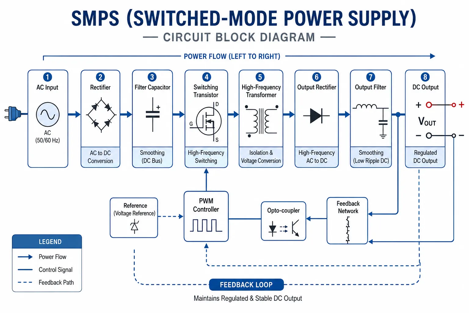
The operating principle of an SMPS is straightforward once you trace the signal path from input to output. The circuit takes an unregulated input (usually mains AC or a raw DC bus), converts it at high frequency, transforms and rectifies it, and then regulates the output through a feedback loop.
Rectifier and Filter
Mains AC (230V at 50 Hz in India) enters the SMPS and passes through a bridge rectifier, which converts it to pulsating DC. A bulk capacitor smooths this into a relatively stable high-voltage DC rail, typically around 310-320V DC from a 230V AC input.
Switching Stage
A power transistor - most commonly a MOSFET or IGBT - switches this DC rail on and off at high frequency, anywhere from 50 kHz to several megahertz depending on the design. At these frequencies, a comparatively tiny transformer can handle the power transfer. That is why SMPS-based supplies are so much smaller and lighter than 50 Hz transformer-based designs.
High-Frequency Transformer
The switching waveform drives a high-frequency transformer, which provides two functions: it steps the voltage up or down to the desired output level, and it provides galvanic isolation between the mains input and the output, which is critical for safety in most applications.
Output Rectifier and Filter
The transformer's secondary side output is again rectified (using fast-recovery or Schottky diodes suited to high-frequency operation) and filtered through an LC network to produce clean DC at the output terminals.
Feedback and Regulation
A control IC monitors the output voltage and adjusts the switch's duty cycle (the ratio of on-time to off-time) through a feedback loop. If the output voltage drops under load, the duty cycle increases to pump more energy through. If the output rises, the duty cycle decreases. This closed-loop regulation maintains a stable output under varying input voltages and load conditions.
Types of SMPS
SMPS circuits are classified by their topology - the arrangement of switching components and energy storage elements. Each topology suits a different combination of input/output voltage relationship, power level, and isolation requirement.
Buck Converter (Step-Down)
A buck converter steps the input voltage down to a lower output voltage. It is the most common topology in point-of-load DC-DC converters - for instance, stepping a 12V rail down to 3.3V or 1.8V for a microcontroller or FPGA. Efficiency can exceed 95% in well-designed buck circuits.
Boost Converter (Step-Up)
A boost converter raises the input voltage to a higher output. Applications include LED driver circuits, battery-powered systems that need a higher rail from a low-voltage cell, and power factor correction stages.
Buck-Boost Converter
A buck-boost can produce an output voltage either above or below the input, which makes it useful in battery applications where the bus voltage varies as the cell discharges. It produces an inverted (negative) output in its basic form; non-inverting variants use four switches.
Flyback Converter
The flyback is the dominant topology for isolated supplies below roughly 100W. It stores energy in the transformer's magnetizing inductance during the switch-on phase and releases it to the output during switch-off. Laptop adapters, phone chargers, and most sub-100W AC-DC supplies use flyback designs because of their simplicity and low component count.
Forward, Half-Bridge, and Full-Bridge Converters
Higher-power isolated supplies (100W and above) use forward, half-bridge, or full-bridge topologies. These push energy through the transformer during both switch phases, making them more efficient at higher power levels. Server power supplies and industrial AC-DC units typically use these designs.
SMPS vs Linear Power Supply

Engineers frequently need to decide between a switched-mode supply and a linear supply. The table below summarises the key differences across the factors that matter most in a lab or production environment.
|
Parameter |
SMPS |
Linear power supply |
|---|---|---|
|
Efficiency |
70-95% |
30-60% |
|
Heat generated |
Low (energy is switched, not dissipated) |
High (excess voltage dropped as heat) |
|
Size and weight |
Compact and lightweight (small HF transformer) |
Bulky and heavy (large 50 Hz transformer) |
|
Output noise |
Higher (switching ripple, typically mV range) |
Very low (near zero switching noise) |
|
Input voltage range |
Wide (auto-ranging 90-264V AC common) |
Narrow (fixed to transformer ratio) |
|
Transient response |
Moderate (limited by feedback loop bandwidth) |
Fast (inherently linear regulation) |
|
Cost |
Lower at high power levels |
Higher at high power levels |
|
Best use case |
General lab, production, embedded, industrial |
Audio, precision analog, RF, low-noise circuits |
For most bench testing applications - powering DUTs, running burn-in tests, or supplying digital and mixed-signal circuits - an SMPS-based supply is the practical choice. Situations where output noise matters critically, such as testing RF front ends or precision analog sensor circuits, may call for a linear supply or an SMPS with additional output filtering.
Advantages of SMPS
- High efficiency: Modern SMPS units achieve 85-95% efficiency, meaning less energy is wasted as heat compared to linear designs.
- Compact form factor: High-frequency operation allows small transformers and capacitors, making SMPS suitable for space-constrained designs.
- Wide input range: Most AC-DC SMPS units accept 90-264V AC, making them universal power supplies usable across different mains standards without manual switching.
- Low weight: The elimination of a heavy 50 Hz transformer makes SMPS-based bench supplies easy to move and mount.
- Regulated output under varying load: Closed-loop feedback maintains stable output even as the load current changes from zero to full rated current.
- Scalability: SMPS designs scale from milliwatts (wearables) to megawatts (industrial drives and data center UPS systems).
Common Applications of SMPS
Understanding where SMPS circuits appear in practice helps calibrate which specification matters most in a given context.
Electronics Labs and R&D Benches
Programmable DC power supplies used for device characterisation, DUT testing, and burn-in testing are virtually all SMPS-based. Units like the ITECH IT6000 series offer remote sense, OVP/OCP protection, and fast programming via LAN or USB, which are standard requirements for automated test systems.
Automotive and EV Charging
Battery management systems, onboard chargers (OBC), and DC-DC converters in electric vehicles rely on SMPS designs, primarily full-bridge and LLC resonant topologies, because of their efficiency at the high power levels involved. Testing these systems requires a bidirectional DC source/load capable of regenerative operation.
Industrial Automation
PLCs, servo drives, and distributed I/O modules are powered from DIN-rail-mounted SMPS units. These must maintain stable output across wide temperature ranges and tolerate mains transients common in factory environments.
Consumer Electronics
Every phone charger, laptop adapter, and set-top box power supply is an SMPS, almost always a flyback design. The shift to GaN (gallium nitride) switching transistors in recent years has pushed charger efficiency above 90% while reducing size further.
Telecom and Data Center Infrastructure
48V DC power distribution in telecom racks and -48V systems in legacy infrastructure are fed from large rack-mounted SMPS rectifiers. Data centers use server power supplies operating at 80 Plus Titanium efficiency ratings (96%+ at half load).
How to Test and Evaluate an SMPS
Validating an SMPS during development or incoming inspection involves measuring several parameters that determine whether the unit meets its specification.
Output Voltage Accuracy and Load Regulation
Measure output voltage at no load, half load, and full load. The difference between no-load and full-load voltage as a percentage of rated output is the load regulation figure. A well-designed SMPS holds this below 0.5%.
Output Ripple and Noise
Connect an oscilloscope with a low-inductance probe tip adapter directly at the output terminals. Measure peak-to-peak ripple at full load. Most bench SMPS units specify ripple below 50 mV peak-to-peak; programmable lab supplies often specify below 5 mV RMS.
Efficiency Measurement
Efficiency is calculated as output power divided by input power. Use a power analyzer or a combination of a precision current shunt and voltmeter on both the input and output simultaneously. For compliance with Energy Star or 80 Plus certifications, measurements are taken at 10%, 20%, 50%, and 100% of rated load.
Transient Response
Apply a load step (for example, from 10% to 90% of rated current) using a programmable electronic load and capture the output voltage response on an oscilloscope. The undershoot, overshoot, and recovery time characterise the feedback loop's bandwidth and stability margins.
Choosing a DC Power Supply for Your Lab or Production Line
Selecting the right power supply comes down to matching four parameters to your application requirements.
Output Voltage and Current Range
Choose a supply whose voltage and current ratings exceed the worst-case requirements of your DUT with some headroom - typically 20% above the maximum expected values. Programmable supplies with wide voltage and current ranges give more flexibility across different test setups.
Noise and Ripple Requirements
For digital circuits and most power electronics testing, a standard SMPS-based bench supply is sufficient. For noise-sensitive analog or RF work, look for supplies with low-noise outputs or hybrid linear-mode output stages.
Interface and Programmability
If the supply will be used in an automated test system, verify it supports the interface your controller needs: LAN (LXI), GPIB, USB, or RS-232. Check the programming speed (how quickly the output settles after a remote command) if your test sequence steps through many voltage or current setpoints.
Protection Features
Look for OVP (overvoltage protection), OCP (overcurrent protection), OTP (overtemperature protection), and output short-circuit protection. For DUT protection in production testing, adjustable protection levels that track the DUT's rated limits are essential.
ITECH's programmable DC power supply range, available through Revinetech, covers outputs from single-channel bench units to multi-channel systems and bidirectional source/load units suited to battery and EV component testing. Each model supports remote sense, wide voltage-current programming ranges, and standard lab interfaces.
Frequently Asked Questions
What does SMPS stand for?
SMPS stands for Switched-Mode Power Supply, also written as Switch Mode Power Supply. The name refers to the high-frequency switching transistor at the core of the circuit.
What is the difference between SMPS and a linear power supply?
An SMPS uses a switching transistor operating at high frequency to convert power efficiently, while a linear supply regulates output by dissipating excess voltage as heat through a series pass transistor. SMPS units are more efficient, lighter, and smaller; linear supplies produce lower output noise.
What is the efficiency of a typical SMPS?
Most modern SMPS units achieve 80-95% efficiency at rated load. High-efficiency designs using GaN transistors can exceed 97% in some topologies. Efficiency drops at very light loads, which is why standby power consumption is separately specified in energy efficiency standards.
Can an SMPS be used to power sensitive analog circuits?
Yes, but with care. The switching ripple from an SMPS can couple into sensitive analog front ends. Mitigation options include using a supply with a low-ripple specification, adding LC filtering at the power entry point of the analog circuit, or using an SMPS followed by an LDO post-regulator for the noise-critical supply rails.
What is the full form of SMPS in a computer?
In a desktop computer, SMPS stands for Switched-Mode Power Supply. The PSU (power supply unit) inside a PC takes 230V AC mains and converts it to regulated 12V, 5V, 5VSB, and 3.3V DC rails for the motherboard, drives, and peripherals. Modern PC power supplies follow the ATX form factor standard and are rated using the 80 Plus efficiency certification system.
Looking for a Bench Power Supply?
Revinetech stocks the ITECH range of programmable DC power supplies, DC electronic loads, and power analyzers, all available with technical support from our applications team in Pune. Whether you need a compact single-output bench supply for component testing or a multi-channel system for EV battery validation, our team can help you select the right specification.